Research Article - (2025) Volume 14, Issue 2
Received: 27-Sep-2024, Manuscript No. JEES-24-149021;
Editor assigned: 30-Sep-2024, Pre QC No. JEES-24-149021 (PQ);
Reviewed: 15-Oct-2024, QC No. JEES-24-149021;
Revised: 19-Apr-2025, Manuscript No. JEES-24-149021 (R);
Published:
26-Apr-2025
, DOI: 10.37421/2332-0796.2025.14.162
Citation: Ahmad, Tausif, Juhi Chaudhary, and Chandra Bhushan Mahto. "GNN-Based Voltage Source Converter Controlled Synchronous Reluctance Motor with Reduced Torque Ripple." J Electr Electron Syst 14 (2025): 162.
Copyright: © 2025 Ahmad T, et al. This is an open-access article distributed under the terms of the creative commons attribution license which permits unrestricted use, distribution and reproduction in any medium, provided the original author and source are credited.
This paper introduces a Generalized Neural Network (GNN) based voltage control strategy for a Voltage Source Converter (VSC) fed Synchronous Reluctance Motor (SyRM) drive system with reduced torque ripples. The aim is to provide an economical, concise, and reliable control method for VSC-controlled SyRM applications. The algorithm utilizes a Generalized Neuron (GN) model created with fuzzy compensatory operators to handle the dynamic capabilities of the drive, thus improving training time. Furthermore, the neuron is decomposed in the synchronous reference frame currents to generate a more accurate set of reference inputs for the active currents component for converter switching. Additionally, the approach avoids conventional pulse-width modulation, resulting in less computational burden on the control. This enables the regulation of converter voltage within a specified time frame to minimize torque ripples. A simulation model of the drive system was developed and evaluated to assess the effectiveness of the proposed method. Both experimental and simulation results demonstrate that the drive system offers rapid speed response and effective disturbance rejection while minimizing torque ripple. The results indicate that the suggested GNN algorithm is efficient and offers technical advantages.
Generalized Neural Network (GNN) • Synchronous reluctance motor • Direct torque control • Torque ripples
The interest in Synchronous Reluctance Motors (SyRM) in the industry is growing due to the intrinsic high efficiency of the motor [1-4]. VSC-driven SyRMs are an excellent choice for a wide range of variable-speed drive systems. While most variable-speed industrial drives currently rely on standard two or four-pole induction motors, they are also compatible with synchronous reluctance motors. The first rotating magnetic-field synchronous motor was introduced by Kostko in 1923 [5]. Traditionally, synchronous reluctance motors are operated directly with a rotor cage, as pure synchronous reluctance motors lack starting torque characteristics [6,7]. However, with advanced inverter technology, appropriate field-oriented control, and Pulse Width Modulation (PWM) techniques, machines without a rotor cage can still be initiated. With the simple structure of the rotor, SyRM can offer high reliability, high overload ability, and high dynamic and high-power density [8-11]. The variable speed drives have provided the efficient application of this motor type, which has convinced the leading manufacturers to introduce their SyRM motor-drive package to the market [12]. On the other hand, the high torque ripples of SyRM have become a challenge for researchers to overcome [13-15]. Many research works are carried out on the design of SyRM to cover this drawback such as in Mostafa A [16]. Moreover, suppressing the torque ripple is viable with a proper control method in the variable speed drives [17,18].
The Field-Oriented Control (FOC) strategy offers an interesting choice for researchers in terms of the control of SyRM with low torque ripple. This is due to the decoupled control of the currents in the synchronous reference frame, which proposes a high-performance control in the steady-state. However, their low dynamic and high computation burdens direct some research work to the other control methods [19,20]. Direct Torque Control (DTC) is one of the alternatives for control of SyRM. The direct control of the torque and flux in the stationary reference frame with the hysteresis controllers and the application of the command voltages by a simple lookup table provides a highly dynamic and straightforward control strategy. However, the high torque ripple and the variable switching frequency of DTC are the undeniable shortcomings of this method. To take SyRM’s high torque ripples into account, the conventional DTC of these motors causes severe torque ripples in the motor. Lack of current controller in DTC’s block diagram leads to high torque ripples. Multilevel inverters have recently been a proper solution for torque ripples, which are studied for DTC in Rashad EM. Another solution that amends the shortcoming of the high torque ripple of DTC is the over-modulation scheme for DTC of SyRM, presented by Zhang et al. This method keeps the simplicity of DTC, and in the meanwhile, decreases the torque ripples and provides constant switching frequency. One more viable approach is the duty ratio regulationbased DTC, which is also known as dead-beat DTC. Basically, the method tries to apply the active voltages not for the whole sampling period, as so the motors’ torque and similarly the flux do not considerably pass the hysteresis limit. This results in a notable reduction in torque ripple with the cost of a little bit of imposing complexity to the method, besides a notably higher switching frequency. A more sophisticated and more robust version of this method is applied by Foo et al. in Michele Degano for the DTC of SyRM. In the rest of this paper, the proposed method is investigated. It presents the simulation results for DTC and the proposed method for the SyRM control.
The SyRM model d-q equivalent circuits, including iron losses and saturation in the synchronous reference frame, are presented in Figure 1. An extra resistor RC connected in parallel with the magnetizing branch in both d and q axes is used to take into account the iron loss effect. The effect of magnetic saturation was also considered in the SyRM model by modeling the d and q axes inductances as dependent on the supply current. It is worth noting that the saturation effect in the d-axis will be distinct from the one in the q-axis since the magnetic paths around the rotor present different reluctances. For this reason, d-q axes saturation behavior will be different with the current variation.

Figure 1. SyRM (a) d equivalent and (b) q equivalent model circuits, which include iron losses and saturation in the synchronous reference frame.
With the growing technologies, the performance of the conventional control algorithms is dissatisfied with the increase of complex and dynamic systems of power electronics in distribution systems and necessitates the use of neural networks as intelligent control algorithms. Figure 1. shows a three-level architecture of intelligent control to operate the switching of power devices of Voltage Source Converter (VSC) in a three-phase system. The three levels are organized as decision making and learning, learning algorithm, and hardware with interface software. Out of the three, the decisionmaking and learning, and learning algorithm levels are the areas of research for the compatibility and efficient control of a nonlinear function system. In the recent trends Artificial Neural Networks (ANN) were used in these levels to overcome the issues of poor power quality in systems under dynamic load conditions [6-9]. However, the performance efficiency of an ANN-based algorithm is bounded in multilayer supervised learning, as it depends on the optimal size of the network and its training. ANN applications are used due to its parallel computing nature and high learning capability in the estimation and regression of the control signals [10-12]. In ANN, generally, summation or multiplication is the aggregation function with linear or non-linear as the threshold function is used by the neuron. ANN algorithms are used to perform nonlinear statistical modelling and provide logistic regression for signal processing in electrical engineering. In back propagation, the Multilayer Perceptron (MLP) neuron uses more aggregation and activation functions which increases the complexity and training time of the algorithm. To reduce this complexity and computation training time both summation and product aggregation functions together output result of the neuron is the function of the output of all activation functions obtained is the Generalized Neuron (GN).
This paper presents a Generalized Neural Network (GNN) structure of MLP to extract the fundamental power current components from the nonlinear load currents required for the estimation of the fundamental reference source currents to generate the switching pulses of an IGBT-based 3-phase inverter. The sigmoid threshold function and ordinary summation or product as aggregation functions in the existing models of ANN neuron structure fail to cope with the nonlinearities involved with the increasing complexity of dynamical systems in real-time monitoring of power quality at the utility end of the distribution system. The existing ANN neuron structure of aggregation function has been modified to obtain a Generalized Neuron (GN) model using fuzzy compensatory operators. Due to this the training time and the dynamic capabilities of the GNN algorithm is better. The impact of unknown nonlinearity on the distribution system has been approximated using GNN to exhibit more accuracy in the improvement of the power quality of the distribution system. Moreover, this paper aims at the performance of intermediate signals to cover different aspects of compensations in power quality improvement.
Concept of generalized neural network
The GNN neuron structure has both summation and product as an aggregation function with linear or nonlinear as the sigmoid threshold function. The combinations of summation neurons and product (π) summation neurons or product neurons in the whole network [2].
A generalized neuron model has been developed that uses the fuzzy compensatory operators [4]. The neuron has both and aggregation functions. The aggregation function has been used with the sigmoid characteristic function while the aggregation function has been used with the Gaussian function as a characteristic function. The final output of the neuron is function of the two outputs OZ and O with the weights W and (1w) respectively.
Figure 2 shows the representation of the summation type GNN neuron structure model. The inputs Xi weighted vector summed by an aggregation function 1. The output of 1 is proceed through an activation function 1. Similarly, weighted inputs are multiplied by the aggregation function. Again, the output of is proceeds through an activation function f2. Summed up these two weighted outputs units. Here two different aggregation and activation functions provide flexibility in the GNN while in the case of ANN regular MLPs single activation and aggregation functions are possible [4].

Figure 2. A three-level architecture of intelligent control.
Architecture of a test system model
There is a series connected load impedance (RL and XL) as a nonlinear load is shown in Figure 3. For power quality improvement a Voltage Source Converter (VSC) with a GNN algorithm is used as a shunt compensator. The SEMIKRON make VSC of IGBT used as a power device is connected across the load using interfacing inductor Lf in each phase at the Point of Common Interface (PCI).

Figure 3. Representation of summation type GNN neuron structure model.
A reference DC link voltage Vdc, DC link capacitance Cdc. Analog filter bank consists of ripple components of series combination of resistance Rr and capacitance Cr respectively, can be seen at PCI for the elimination of high frequency switching noise of power devices as well as low order harmonics of the source (Figure 4).

Figure 4. Architecture of three-phase inverter system controlled through GNN algorithm.
Control GNN algorithm
The GNN control algorithm for the operation of the VSC is proposed to extract the weighted power current components from the load current to estimate the reference source current. The model uses summation (1) and product (π) neurons with unknown weights (W1) and (W).
The total number of weights needed is twice the number of inputs plus one, obtained through online training.
Develop a GNN control algorithm for the extraction of Active current components from load current to generate reference source current for the switching of an Active Power Filter known as DSTATCOM.
Part 1: Analysis at the input stage
Inputs are sensed load currents at PCC: ILa, ILb, ILc.
Input weights are calculated templates: ua, ubp, ucp.

Sigmoidal function of summation;
Gaussian function of product;

Weights associated with;
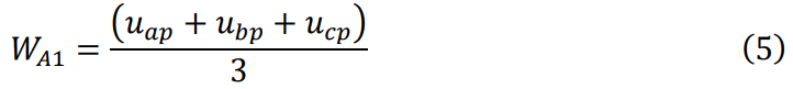
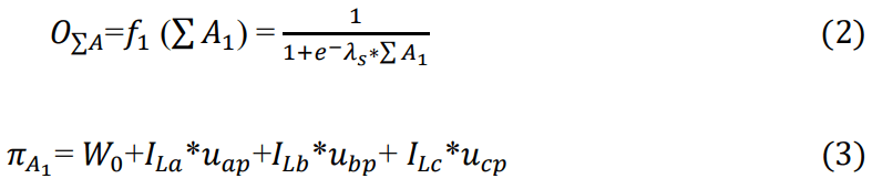
GNN output of input stage,

Part 2: Learning at the input stage
Error to the desired output of GNN,

The sum squared error for the convergence of all patterns is,

where eLpa, eLpb are eLpc phase A phase L and phase A errors.
Reverse pass for modifying the connection strength, i.e., to update weights
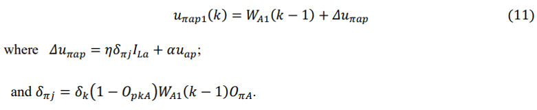
Weight associated with A1, is given by
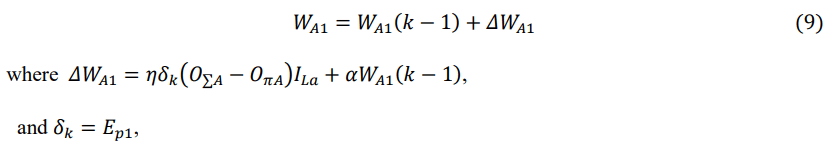
Weight associated with the input of the A1 part of the summation GNN,
where ±: momentum factor, 5: learning rate.
(b) Weight associated with the inputs A1 part of the summation GNN,
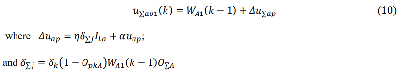
Weight associated with the input of the A1 part of the summation GNN,
Part 3: Analysis at intermediate (Hidden layer) stage
Inputs are the GNN outputs of the input stage, ILap, ILbp and ILcp.
Weights associated with the intermediate stage A2 are ap1, bp1 and cp1 respectively.
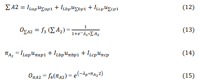
Weights associated with A2;

GNN output of input stage,

Part 4: Learning at the intermediate stage
Error to the desired output of GNN,

The sum squared error for the convergence of all patterns is,

where eLpa1, eLpb1 are eLpc1 phase ‘a’ phase ‘b’ and phase ‘c’ errors at the intermediate stage.
Reverse pass for modifying the connection strength, i.e., to update weights at the intermediate stage:
(a) eWight associated with ΣA2, is given by
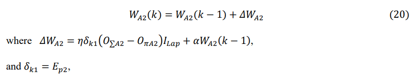
where α: momentum factor, 5: learning rate.
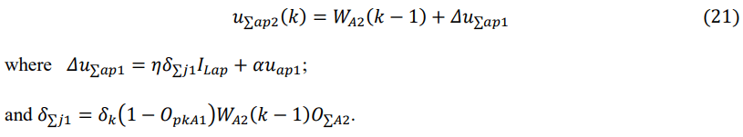
(b) Weight associated with the inputs ΣA2 part of the summation GNN,
(c) Weight associated with the input of the πA1 part of the summation GNN,
Weights associated with ΣA2;

By applying all these equations in the GNN algorithm we can generate a gate pulse that controls the IGBT-based voltage source converter output which is given as input of the synchronous reluctance motor and so on controls the torque as per reference signal.
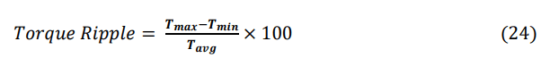
Following the creation of the simulation plot, we analyze the torque of the SyRM and subsequently calculate the torque ripple. This assessment helps in understanding the motor's performance characteristics and identifying potential areas for improvement in its design and operation.
The study is performed on the simulation of a 3-phase SyRM which is controlled through IGBT-based three-phase converter (Figure 5). In this the Machine specification is given as machine is of 2 poles in which the stator d-axis and q-axis inductance is 0.05 and 0.0051 Henry, stator resistance is of 0.33 ohm. Its control parameter is given such that we get results as:

Figure 5. Current waveform of GNN control.
The control of systems by the Direct Torque Control (DTC) method has an undesirable chattering phenomenon. The GNN-based control method has been chosen, and this is a Generalized Neural Network (GNN) based algorithm for voltage source converter controlled reduced ripple torque. The GNN algorithm is modified to obtain a Generalized Neuron (GN) model using fuzzy compensatory operators. This modification improves the training time and dynamic capabilities of the GNN algorithm. In addition, it ensures that the desired performance is maintained and that there is a better convergence accuracy (Figure 6).
Figure 7 depicts the reference torque applied to the control system of the SRM. The forthcoming analysis will focus on evaluating the response of the SRM under both direct torque control and the control method based on Generalized Neural Networks (GNN). This analysis will be based on the data obtained from simulation results.

Figure 6. Reference torque.

Figure 7. Torque control through DTC method.
In Figure 8, the simulation result of the direct torque control method reveals a notable presence of torque ripple. This undesirable characteristic has prompted the implementation of the Generalized Neural Network (GNN) method as a new control approach aimed at effectively mitigating this ripple (Figure 9).

Figure 8. Torque control through GNN method.

Figure 9. Combine torque control through DTC and GNN method.
The algorithm for controlling reduced ripple torque in voltage source converters is based on the Generalized Neural Network (GNN) (Table 1). The simulation result illustrating the GNN-based torque control is presented in Figure 7.
| Method of control | Tmax | Tmin | Tavg | Torque ripple |
| MTPA | 64.27 N-m | 40.17 N-m | 52.2 N-m | 46.17% |
| DTC | 55.16 N-m | 44.46656 N-m | 49.813278 N-m | 21.47% |
| GNN-control | 51.1835 N-m | 49.50121 N-m | 51.14 N-m | 3.29% |
Table 1. Torque ripple calculation for 0.5-0.52 sec for both DTC and GNN control.
In Figure 10, the simulation results combine both torque control techniques for comparison. It is evident from these results that the GNN control approach closely approximates the reference signal. Furthermore, a separate analysis was conducted using a different reference signal, as depicted in the subsequent Figures 11-14.

Figure 10. 2nd Reference torque.

Figure 11. Output of torque control through DTC method based on 2nd reference torque.

Figure 12. Output of torque control through GNN method based on 2nd reference torque.

Figure 13. Combine torque control through DTC and GNN method based on 2nd reference signal.

Figure 14. Output current on the base of 2nd reference torque.
In this work, we addressed the problem of torque ripple reduction in a synchronous reluctance machine. We have based our approach on control-based solutions. In a cascade velocity/currents control strategy, we first proposed a new reference current. To examine the contribution of this method on torque ripple reduction, we compared it to two methods used in the literature, namely the direct torque control and GNN-based algorithm for voltage source converter control. The simulation results clearly show the effectiveness and superiority of this proposed method in reducing the torque ripple of the machine.
In this paper, our focus is on the reduction of torque ripple through the application of a sophisticated Generalized Neural Network (GNN) based algorithm. This advanced algorithm is specifically engineered to intricately control the gate pulse of the voltage source converter, resulting in a significant reduction in torque ripple.
[Crossref]
[Crossref] [Google Scholar] [PubMed]
Journal of Electrical & Electronic Systems received 733 citations as per Google Scholar report