Research - (2021) Volume 10, Issue 8
Metal forming process such as extrusion, rolling, sheet metal forming etc. where the work piece are subjected to finite strain and stress. Metal forming is an ancient art and is a vast subject of closely guarded of secrets in antiquity. In many respects the old craft traditions have been retained until present time. Unfortunately, a series of problem arises when commissioning a new production or when changes made from one well known material to another. Current trends towards adaptive control and flexible manufacturing systems call for more precise definition and understanding of the process. This will ensure much better control over a production, dimension and quality. Practical test to determine the best tool shape and forming condition can be very expensive and wasteful of tool and work piece material. Many cases of simple component forming operations may result in cracking during production or become weakened by high residual stress. In view of above, aluminum sheet metal forming has been active subject for the past three decades and current trends indicate importance of the sheet metal forming operation, since it has applications in automotive and aero industries. Major problem in aluminum sheet metal forming operation were deformability and spring back effect. Deformation errors and spring back effect are dependent on the number of parameters such as die and tool geometry, friction condition, loading condition and anisotropic properties of the metal. Computer modeling of sheet metal forming of aluminum sheet metal will help in predicting deformity error and spring back effect which saves lot of money and time due to the prediction gives accurate results.
• Sheet metal • Deformation • Bauschinger effect • Anisotropic hardening
In automotive and aero industry, significant effort is being put forth to utilize an aluminum alloy sheets for their applications. Since lighter in weight, aluminum sheets would improve the fuel efficiency. However, there are several major technical hurdles to overcome in aluminum applications besides higher material cost. They are inferior formability and large spring back of aluminum sheets. Introducing computational methods based on finite element method in the design stage to analyze the forming process of an aluminum alloy sheets is one way to overcome those drawbacks. In classical plasticity the yield function that present a convex yield stress surface in the stress field which limit the elastic range of material [1-6]. The proper measurement and description of the initial yield stress surface and its evaluation are essential for the constitutive law in plasticity. Since the yield surface, especially its evolution is difficult to measure; isotropic hardening of the initial yield surface is commonly assumed in the theoretical plasticity. Under such assumption, the initial yield surface expands radially or proportionally in the stress field during plastic deformation. This assumption is reasonably effective to predict plastic deformation, especially when the deformation of the material is approximately homogeneous and proportional. If the material undergo non monotonous deformation, the assumed isotropic hardening might not be so effective even though deformation is approximated proportionally. When a sheet metal is removed from the tool after forming, material experiences an elastic unloading and spring back. During the reverse loading material usually demonstrate a Bauschinger effect. The Bauschinger effect is related to the translation of the yield stress surface. The isotropic hardening assumption therefore doesn’t properly predict the Bauschinger effect and the spring back. Assuming the initial yield stress surface to translate in the stress field without changing its shape and size during plastic deformation is another way to simplify evaluation of the yield stress surface i.e. kinematics proposed by Prager and Ziugler [7,8]. In order to describe the expansion and translation of the yield stress surface during plastic deformation, the combination of isotropic and kinematic hardening is also commonly used [9]. In metal forming process friction condition must be controlled in order to successfully increase high quality parts with high efficiency. The various methods for determining the friction condition have been introduced through the many years. The most well-known method in determining the friction condition is bulk forming i.e., the ring compression test [10,11].
The forming limit diagram (FLD) which gives limit strains of sheet metal under various strain paths form balanced biaxial stretching to uni-axial tension. FLD is commonly used to evaluate the forming limit in sheet metal forming processes. On the other hand theoretical approach to predict the forming limit of sheet metal has been proposed by many investigators. However, they have not been able to sufficiently give the FLD which fits the measured one in the old region of strain path [12,13]. Marciniak and Kuczynski [14] have introduced a pre-existing inhomogeneity in sheet metal and enable the calculation of the development of localized neck in stretching region. By the M.K. analysis the limit strain near the balanced biaxial stretching is predicted to extremely large compared with experimental value [15,16]. Storen and Rice [17] have given the limit strain in the old region of the strain paths by using a simplified constitutive model of a pointed vertex on subsequent yield loci. In the S.R. analysis of the work hardening, exponent is decisive of the FLD and the FLD predicted does not always fit the measured ones in great variety. The M.K. and S.R. Model have been improved by great number of subsequent investigators. Considering yield criterion on yield surface curvature with quadratic yield function, Needleman and Triantafyllidis N. Void [18-22] employed the constitutional model for porous plastic material [23]. Padwal and Chaturvedi [24] used Hosford yield criterion with planar anisotropy. Many yield function have been defined in order to represent elastic limit and subsequent plastic deformation for different sheet materials. Quadratic Hill [25] was successfully applied for steel sheets over a long period and is still widely used. The parameters for Hill model are usually determined by uniaxial tensile test at 00, 450 and 900 with respect to the rolling direction. The anomalous behaviour of aluminum for which equi-axial yield stress was higher than uni-axial yield stress when ‘r’ value was less than one [26]. This is in contradiction to Hill model and it clearly showed that anisotropic behaviour of metal in general should not be based on uni-axial test only. Subsequent models by Hill [27] improved the description of yield locus. For instance, aluminum can be considered the equi-biaxial yield stress as a parameter.
The use of appropriate anisotropic yield criterion suitable for sheet metal forming to predict material behaviour accurately, anisotropic yield function associated with the work hardening rule has been postulated. The quadratic anisotropic yield criterion by Hill [25] has been the most popular choice to represent planar anisotropy. Several non-quadratic criterions were developed by Hill, Hershey, Hosford and Bassani [28-31]. Each criterion has its own merit for the specific applications. However, most of them have some limitations to represent planar anisotropy for wider application. Sowerly et al. [32] suggested a modeling of a sheet metal stamping operation to predict the approximate strain needed to deform a sheet from flat to the final shape of the stamping. In previous papers dealt with elastic plastic analysis of a large deformation problem such as stress strain rates, usage of proper formulations for materials and geometrical non-linearities etc [33]. Omura, Tabota and Shima [34] studied the deformation behaviour of a laminated sheet metal, as in the upper bound method based on Hill’s plasticity theory. The r-value and the stress strain curves are derived theoretically. Experimental results are then compared with the theoretical one, which is a good agreement.
Tan, et al. [35] studied the effect of anisotropy on pure bending of the sheet metal. Anisotropy is known as the variation of the mechanical properties with respect to orientation in sheet metal due to the preferred crystallographic orientation. It is an important parameter to be considered in simulating the bending process. Dadras and Maijlessi [36] explained the Bauschinger effect theoretically and experimentally. Bauschinger effect was based on the linear stress strain approximation for fibers in reverse loading. It is also noted that different materials respond to the Bauschinger effect in different ways, so that a specific model should be applied with caution. Material thinning in bending is mainly due to the effect of Bauschinger and strain hardening. Higher the strain hardening rate, greater the reduction in the thickness. Greater thinning is predicted when the Bauschinger effect is considered. The anisotropic constant has a very limited effect on thinning [37-42]. Gau and Kinzel [43] presented a new model for a spring back prediction for aluminum sheet metal forming. It is based on isotropic and kinematic hardening models. A simple low cost multiple bending experiment has been developed to determine the material parameter for aluminum alloys. The new model fits the available experimental results better than isotropic and kinematic hardening model and MROZ multiple surface model. Yoon et al. [44] and Barlat et al. [45] explained plane stress yield function for aluminum alloy sheet in 2 parts. Part I, describes anisotropic behaviour of aluminum alloy sheet was implemented in a finite element code. The simulation of cup drawing process for the aluminum sheet was performed to compute the cup height profile with different yield functions. The predicted profile was compared to experimental data and the best agreement between theoretical and experimental results was obtained. In second part, the load punch displacement curve and sheet thickness profile along the different radial direction of the cup were shown to be in excellent agreement with experimental data. Vegter and Boogaurd [46] presented anisotropic plane stress yield function based on the interpolation by 2nd order Bezier curves. The parameters for the model are exactly derived by four mechanical tests.
Namely uni-axial, equi-biaxial, plane strain tensile and shear test. The set of test repeated for number of directions. The relevance of an accurate description of yield locus and the flexibility of the proposed yield function are demonstrated by prediction of forming limit diagram. It is demonstrated that the sensitivity of forming limit diagram to small changes in yield locus can also be used to determine some of material parameter by inverse analysis.
Metals and alloys exhibit a greater variety of mechanical behaviour under different loading conditions. The knowledge of mechanical behaviour of materials plays a vital role in engineering stress analysis and design. The study of elastic and plastic behaviour is very important to understand the manufacturing process of components. For the metals, initially it behaves as an elastic material. When the load applied is beyond elastic limit, the material begins to flow plastically. Applying suitable yield criteria, one can identify the onset of plastic deformation. In the sheet metal, the plastic deformation is essentially a permanent deformation and also it is time independent. The material behaves in a non-linear fashion in the plastic region. It can be an ideal plastic, elasto-plastic or elasto-visco plastic. In ideal punching operation of sheet metal forming, the material behaves as elasto-plastic material. The application such as hot extrusion or hot sheet metal forming, where the material works above recrystallisation temperature may be modeled as elasto-visco plastic material. For different practical applications researches are used elasto plastic model as well as elasto visco-plastic model.
Establishment of plastic deformation and formability of sheet metal components are of primary importance of any sheet metal forming plants. Several important material parameters directly influence the forming and fracture behaviours of the formed parts. The choice of appropriate mechanical characteristics is as important as the design of tooling and setup of press lines. Also the material characteristics dictates among the two things, whether the part can be formed in one or multiple stages, the clearance requirement, the degree of spring back and further the influence of thickness on the hardness distribution of the manufactured p arts.
Homogenous body has uniform properties throughout the body i.e., properties are not a function of position in the body where as a nonhomogenous material has non-uniform properties over the body. Orthotropic material has three mutually perpendicular planes of material symmetry. If at every point of material, there is one plane in which the mechanical properties are equal in all direction, such material is known as transversely isotropic. For sheet metal forming operation, materials are considered as anisotropic homogenous materials. In this paper a study on different mechanical properties of the aluminum material for sheet metal forming operation are discussed. Mechanical properties are determined experimentally.
A uniaxial tensile test are often carried out on the sheet metal specimen and some time on finished parts in order to evaluate the parameters which can directly be correlated to the part behaviour under complex forming conditions. The laboratory test simulate simple deformation condition carefully devised mathematical model which permit to predict the deformation behaviors under complex stress conditions, which are the norms of actual industrial practice. Important material properties to be considered during sheet metal forming operation are work hardenability factor, work Harding index 'n', anisotropic parameter 'r', strain rate ‘ε’, yield strength ‘σy’, and young's modulus ’E’ and ultimate stress ’σe’.
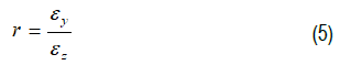
In order to understand the behaviour of materials under complex stress conditions, the uniaxial stress problem is first dealt with non-zero principal stress components. Consider a thin plate of length ' ' width 'b' and thickness ’t’ is subjected to axial load 'P'. The stress in axial direction is P/tb. The axial strain component, a is where is the change in length due to loading. Due to the conservation of mass there is a change in strain both in width as well as thickness direction. The strain in width direction, is the transverse strain, b. Ratio of transverse strain to axial strain is known as Poisson’s ratio. Similarly the strain in thickness direction, t is . The ratio of strain in thickness direction to width direction is known as anisotropic parameter or ‘r’ parameter.
The 'r' value is a measure of the ability of material to resist thinning. High 'r' value indicates the material with good forming properties, which mean less deformation along thickness direction for high 'r' values. Cold sheet metal work exhibits different properties when measured along the plane of the sheet. The mechanical properties are different in the three directions and 'r' value could be other than unity is called anisotropic material.
Hardenability factor describes the specific relationship between the subsequent yield stress (y) of the material and plastic deformation accumulated during and prior to plastic loading. Number of hardening models of the material is available in literature and some of them are classified as elastic linearly hardening model, elastic exponential hardening model, Ramberg-Osgood model in which Bauschinger experimental loading model is commonly used for elastic plastic material.
In the elastic linearly hardening model the tangential modulus is assumed to be constant and stress strain relationship is approximate by two straight lines. That is:
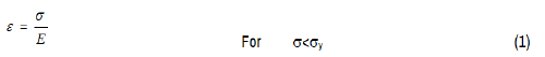

Where Et is the slope of the elasto plastic region.

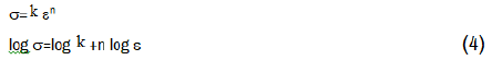
Second term in equation (2) indicates plastic deformation of materials and Et is the corresponding young's modulus in elastic plastic region. e is the elastic limit stress. In many practical applications, these models are used. In elastic limit the hardenability factor is assumed to be one. Elastic exponential hardening model relate stress strain in two parts i.e. elastic region and elastic plastic region. In elastic plastic region
Where k and 'n' are the material constants determined experimentally. The parameter, 'n' is considered as the hardenability index and k is the hardenability factor.
Work hardening rules are described in many ways. Isotropic hardening rule states that a progressively increase in yield stress under both tension and compression. Kinematic hardening rule states that the difference between yield stress under tensile loading and compressive loading remains constant.
Independent hardening rule states that the subsequent yield stress under tension loading and compression loading are independent to each other, thus hardenability parameter, k and hardenability index 'n' are used to represent the different types of plastic deformation. Considering elastic exponential hardening model, for isotropic hardening model,
Which indicate that the work hardening index 'n' is the slope of ε and curve plotted in a log-log space. While the intercept of curve gives log k. The parameter 'n' value give the characteristic of stretching operation, since it provides the measure of the ability of the material to distribute the deformation uniformly. On other hand, K value provides some indication of level of strength of the material and hence the magnitude of the forces required in forming.
For most of the ductile material, the strain hardening co-efficient lies in between the range 1 to 1.5. Higher the 'n' value means greater uniform elongation less localized deformation and larger rate of hardening. The ‘n’ values of the material are also referred to work hardening exponent and are directly proportional to the ductility of the material. It is observed that the decrease in yield stress increases 'n' value. Increase in 'n' value saturates at certain level. It is obvious that, spring back effect is also less for the larger value of 'n' values.
The strain hardening coefficient, ‘n’ and the ‘r’ parameters values have been used for the characterization of sheet metal forming operation. 'r' value indicates good deep drawability whereas 'n' value indicates good deformation characteristics. Since many commercially important forming operations [47] are carried out in 2-Dimensional strain space, two dimensional strain spaces are represented by major strain axis. The forming limit during plane strain stretching occurs at the intersection of this axis. The minimum in the forming limit curve lies close to the plane strain limits. Hence, a simple and effective method of determining 'r' and 'n' parameter is needed.
A series of tensile test have been carried out on specimen of locally available material aluminum of different thickness. It was cut from the sheet as shown in Figure 1 as specified by ASTM standard. For determining the 'r' values the condition of volume consistence was imposed. The procedure adopted is as follows:
Figure 1. Tensile test specimen.
Four equi-spaced horizontal lines were scribed with in the gauge length of specimen. The specimen was held in the jaws of Hounsfield Testing Machine. Initial distances between the scribed lines were measured with the help of cathetometer. The measurement of width was made using micrometer. The measurement of width was done above and below scribed lines and also the width near all the scribed lines was measured. The loading was stopped just near the peak load that is determined by trail test. The measurement was repeated and details of experimental results are recorded.
From the experimental data strain in X direction and Y direction are computed. Strain in Z direction is determined by adding the strain in X and Y direction with negative sign, since
 Then 'r' value is determined from the formula.
The deformation forces verses elongation has been directly obtained from the Honsefield testing machine. The following equations are used in determining engineering stress [48,49].
where P is the deformation force in Newton and Ao is the original cross section area. Engineering strain,

where L and Lo represent original gauge length and instantaneous gauge length respectively. Hence, true stress

And true strain
Where ‘e‘ is engineering strain
It is noted that the above equation holds good up to the point of specimen necking. The true stress is determined by measuring the actual load and cross sectional area where, cross sectional area is the instantaneous cross section area corresponding to the load. Similarly true strain is depends on the actual area by measuring width and thickness.
where A0 is the initial area and A is the changed area.
The log-log plot of true stress and true strain is plotted from the experimental data. A best fit straight line curve has been drawn connecting the points. Slope of these lines gives 'n' values representing the work hardening index of the material. Strength parameter can be obtained from the intercept of the straight line in y-axis.
For example consider the flow curve equation
Taking log:

This represents a straight line curve which intercepts at log k when the curve is plotted in log (σ) -log (ε) space. Figures 2 and 3 illustrates the engineering stress strain (applied load divided by original cross section area) curve for thickness 0.5 and 3.10 mm respectively. The true stress and strain (applied load divided by current cross section area) is indicated in Figures 4 and 5 of the thickness 0.5 and 3.1 respectively. Figures 6 and 7 illustrate the logarithmic plot of true stress and strain curve. Similar graphs are obtained for different thickness and hardenability factor , hardenability index ‘n’ and ‘r’ parameter are obtained.
Figure 2. Engineering stress-strain curve.
Figure 3. Engineering stress-strain curve.
Figure 4. True stress-strain curve for 0.5 mm thick Aluminum sheet metal.
Figure 5. True stress-strain curve for 3.10 mm thick Aluminum sheet metal.
Figure 6. Logarithmic plot of true stress true strain for 0.5mm thickness.
Figure 7. Logarithmic plot of true strain for 3.10 mm thickness.
‘r’ values, ‘n’ values and hardenability factor all are characterized by material properties is given in Table 1 for different thickness. The average value of strain tor k=9.3468, strain hardening index n=1.3843. Figure 8 shows the photograph of the test specimen before and after failure.
| Thickness (mm) | r value | n value | K value |
|---|---|---|---|
| 0.5 | 0.03495 | 1.4124 | 9.7852 |
| 1.23 | 0.5657 | 1.3701 | 8.8665 |
| 1.27 | 0.31726 | 1.3906 | 9.2894 |
| 1.34 | 0.179178 | 1.4069 | 9.8837 |
| 2.94 | 0.295757 | 1.3437 | 8.333 |
| 2.99 | 0.20839 | 1.3893 | 10.121 |
| 3.10 | 0.031305 | 1.3773 | 9.149 |
Figure 8. Tensile testing specimen.
Average value of Tangent modulus ET is obtained as 220 Mpa. The Young’s Modulus E=80 GPa and Poisson ratio=0.3.
In metal forming operation the flow of material within the body is responsible for bringing about permanent shape change. Material properties of sheet metal play an important role in the forming operations. In view of the above statement mechanical properties of aluminum material such as hardenability factor, hardenability index, anisotropic parameter, yield stress, young’s modulus and tangent modulus were determined experimentally. The experiment is carried out on Honse field tensometer. The percentage error from the experimental result to the available result in the literature is within 3%. The variation of the results may be due to the non-homogeneity of the locally available aluminum sheet metal and other operating conditions. Specimens are prepared as per the ASTM standards for uni-axial tension testing of aluminum materials. Number of specimen were prepared and tested for various thickness of the sheet metal. Strain hardenabilty factor=9.34, strain hardenabilty index 1.38, young’ modulus, E=80 Gpa and Tangent modulus ET=220 Mpa and Possion’s ratio=0.3 were obtained.
We are thankful to the Management of Shree Devi Institute of Technology, Mangalore and National Institute of Technology, Karnataka, Surathkal, India, for the support to carry out the experimental work.
Journal of Material Sciences & Engineering received 3677 citations as per Google Scholar report