Research Article - (2021) Volume 0, Issue 0
Received: 08-Dec-2021
Published:
29-Dec-2021
Citation: Huseynob, Mahmud. "Integrated Design of Active and Passive Gripper for Robotic Pick and Place Applications." Adv Robot Autom S8 (2021):002.
Copyright: © 2021 Huseynob M. This is an open-access article distributed under the terms of the creative commons attribution license which permits unrestricted use, distribution and reproduction in any medium, provided the original author and source are credited.
Serum Grippers developed in recent years either cannot achieve a complete universality due to grasping stability issues or are designed with excessive complexity. In this paper, the design of a three-fingered tendon-driven integrated gripper based on the concept of integrating Universal Active Gripper (UAG) with Universal Passive Gripper (UPG) fingertips, which ensures achieving adjustable fingertip stiffness and is practically proven to solve grasping stability issues, is proposed. Furthermore, kinematic, dynamic, and force analyses was conducted to calculate the specifications of the designed gripper, which was compared to four commercial grippers. Finite element analysis was also carried out for the designed gripper. When the final design of the gripper was compared to that of Hou et al. (the only comparable design present for the integrated gripper), one crucial similarity noted was based on both designs adopting the same kinematic configuration. This fact further increases the confidence in the optimal development of the designed gripper. According to FEA results, the maximum stress acting on the components of the gripper was 15.78 MPa, 39.45% of the yield stress of Acrylonitrile Butadiene Styrene (ABS). In conclusion, it was theoretically established that the designed gripper with the tendon-driven actuation is operating efficiently.
Universal gripper • Three-fingered • Integrated design • Active gripper • Passive gripper • Tendon driven
Robots are increasingly demanded by industries. According to the International Federation of Robotics IFR, the average robot density in industries has hit a new global record of 113 units per 10,000 employees. This was 74 units per 10,000 employees just five years ago based on IFR. All industrial robots need a unique tool to perform tasks, known as an effector, mounted onto the 'end' of the robot; the end effector. For pick and place applications, grippers are chosen to be the end effector. In the early development of grippers (in the 1970s), designed grippers were dedicated to a single task, which is pointed out by Eitel, where she reports how industries had to buy several grippers, and each gripper was used to deal with a specific object[1-3]. This in turn, increased the cost of robotisation. Nowadays, all commercial grippers are designed specifically attempting to be more universal to decrease robot costs.
A great variety of grippers, with significant distinction in their conceptual design, were found during the literature review. Monkman et al., classify the grippers into two major categories: those that apply no actual grasping of the object but rather holding of the object and those that apply real grasping of the object. The first category of grippers is well described by Gitesh and Narayan [4,5]. According to them, vacuum grippers (uses suction effects), magnetic grippers (uses magnetic effects to lift ferrous objects) and adhesive grippers (uses adhesive effects to provide sticking action) are the sub-categories of this category of grippers. These grippers are less versatile in terms of handling objects because vacuum grippers are sensitive to porous surfaces, adhesive grippers can suffer from dirt and dust, and magnetic grippers can only handle ferrous objects [6]. The second category of grippers is well presented and there are two main subcategories accordingly:
• Active grippers (also called anthropomorphic grippers or robot hand). Pham and Yeo note that ‘active grippers imitate basic prehensile modes of human fingers’ and that they use normal forces to generate static frictional effects to grasp objects [7].
• Passive grippers, which are less widely spread with respect to other type of grippers. Amend et al. highlight that passive grippers use the jamming effect and magneto rheological effect to grip objects [8].
Both grippers (passive and active) can be referred to as universal grippers; thus, they can be defined as Universal Passive Grippers (UPG) and Universal Active Grippers (UAG). Although recently some new designs are being presented for both universal gripper types, e.g., soft pneumatic grippers studied by Kim and Cha and meshed pin array grippers researched for UAG and UPG, respectively, the widely accepted structure for both universal grippers are shown (Figure 1) [9,10]. Amend et al. affirms that UPGs are simple to use, very fast, require minimal visual processing of their environment and have high error tolerance. Brown et al., contributes by mentioning the stiffness adjusting ability of the membrane that UPGs have, which allows them to have the right stiffness at the point of contact, whose benefits are stressed by Qiao et al. He has established how doing so solves the issues with the unstable grasping of the object. However, UPGs has some severe drawbacks. Yun et al. describes how objects that are bigger than the gripper must be gripped in the center of the mass for stable gripping conditions, which is an impossible task for objects that have their center of mass outside their shape. Amend et al., further examines the accuracy issues of UPGs. He finds that UPGs have a low pick and placing accuracy (up to 3 mm error), and they twists the objects being gripped by 6-8 degrees on average between tasks [11-13].

Figure 1. Shows the labelled image of UPG and UAG (A) Image of UAG while picking an object (B) Image of active gripper.
On the other hand, two main types of UAGs were developed, which differ by their driving mechanism: tendon-driven (cable or string-driven) and non-tendon-driven (gear driven) grippers (Figure 2). During more critical research, it was found that the main reason why so many designs and alternatives are presented for UAGs is due to a single reason: grasping stability which threatens universality. Non-tendon-driven UAGs are usually more complex to design but allows one to have complete freedom in terms of independently controlling joint torques and induced force on the object. Thus, this allows stable grasping but at a cost of highly complicated position and torque control of each joint. Ueda et al. and Fukui et al. have designed a full non-tendon-driven robot hand with four fingers (12 DOF) and five fingers (20 DOF), respectively. They both have allocated a dedicated PC for the computation of the control algorithms for the grippers [14-16].

Figure 2. Shows the two types of UAGs 9 (A) Non-tendon-driven UAG (B) Tendondriven UAG.
On the other hand, tendon-driven UAGs require a smaller number of active joints; thus, they are easy to design and build. But it is hard to achieve grasping stability with this kind of UAGs alone because unlike nontendon- driven UAGs, these grippers don’t have direct control on the contact force. One approach is to integrate them with grasp planning algorithms and perfectly calibrated sensors, which is based on the concept of increasing the contact area between fingers and the target object to achieve grasping stability. Kaijen et al., [17] and Hsiao et al., [18] have tried this approach. However, it was not always possible to maximize the contact area. Even worse, some objects like transparent glasses or shiny objects were failed to be grasped due to sensor vision problems. The second approach to increase stability with this type of grippers is recommended by Pham and Yeo (1991). They claim that interchangeable fingers can be used, each with different stiffness to allow the gripper to deal with instability issues. This concept is based on achieving different contact stiffnesses with various target objects to ensure a flat or concave contact area. Although this approach is more straightforward than using highly complicated non-tendon-driven grippers and more successful than using tendon-driven grippers with grasp algorithms, it still requires manual changeover between processes and may be inappropriate for quickly varying environments [19].
Accordingly, the third approach is adding on Pham and Yeo (1991)’s approach and automating the process of adjustable contact stiffness. This can be done by integrating a UPG fingertip to the tendon-driven UAG. As UPG’s are simple to control, and allow adjustable stiffness in the contact area, this approach would eliminate complex torque and motion algorithms and expensive hardware that a non-tendon-driven UAG requires. Also, by benefitting from adjustable stiffness fingertips, integrated gripper would ensure highly universal and stable grasping, unlike tendon-driven grippers. Doing so would allow designing a gripper that carries the benefits of both UAG types. As Hou et al. and Qiao et al. have already proven the positive effects of an integrated gripper, this paper does not seek to re-investigate these effects. Instead, this paper aims to design the tendon-driven integrated gripper and compare the specifications of the designed gripper with those of other grippers to establish that the designed gripper with the new actuation mechanism will operate efficiently and at a comparable performance to nontendon- driven grippers [20].
List of requirements
To achieve the aims of the project, the set requirements had to be satisfied, and the failure of the project would be caused by:
• Design specifications: If the designed gripper is larger than other grippers; cannot grasp large objects that are easily graspable by other grippers; or is heavier than other grippers.
• Force and dynamic specifications: If the tendon actuation mechanism (e.g., strings, DC motor, etc.) fails to provide comparable grasping forces, operating speeds, or acceleration.
• Tendons: If the selected tendons of the gripper cause desynchronisation of input motor speed (or torque) with output fingertip velocity (or force) due to elastically yielding.
To establish the three points above, specifications of other grippers must be noted. Kinematic, dynamic and force analysis must be conducted. The achieved list of specifications must be calculated and compared to that of other grippers.
• Mechanical stress: If the designed components of the gripper fail due to the mechanical loads acting on them while the gripper is operating. Thus, FEA analysis must be conducted and discussed.
Thus, successfully meeting the criteria set above, the designed gripper can be theoretically established to be efficient.
Target specifications of the gripper
Specifications of multiple commercial UAGs were researched and those data was extrapolated to set a reasonable list of target specifications for the newly developed gripper. The research was conducted based on four commercial grippers and is presented (Table 1). A list of target specifications was set accordingly (Table 2).
| Model | Speed (mm/s) | Grasping time (s) | Travel (mm) | Weight (kg) | Payload (kg) | Overall dimension (mm) |
|---|---|---|---|---|---|---|
| Robotiq (2021) | 22-110 | 1.4-7 | 0-155 | 2.3 | 10 | 244 × 172 |
| On robot (2021a) | 125 | 0.5 | 0-180 | 1.15 | 10 | 156 × 158 × 180 |
| On robot (2021b) | 38-127 | 0.06-0.21 | 0-110 | 0.78 | 2 | 213 × 149 × 36 |
| Robot shop (2020) | Unknown | Unknown | 0-67 | Unknown | 1.5 | 112 × 130 |
| Spec name | Spec values | Spec units |
|---|---|---|
| Number of fingers | 3 | (pcs) |
| Actuation approach | DC motors and pneumatic | (no unit) |
| Fingertip speed (min) | 50 | (mm/s) |
| Grasping time (max) | 5 | (s) |
| Travel (min) | 0-60 | (mm) |
| Gripper weight (max) | 1 | (kg) |
| Payload (min) | 1.5 | (kg) |
| Overall dimensions (L*∅)(max) | 250 × 180 | (mm) |
| Clamping force of gripper [min] | 30 (assuming contact friction coefficient of min 0.5) | (N) |
| * dimension of gripper range |
Design
The final designed gripper has three identical kinematic chains, equally spaced 120 degrees apart so that they are symmetrical from the top view. The kinematic chain of the gripper can be split into four parts: Base, driving mechanism, finger, and fingertip. These parts are labeled, where a crosssection view of one of the kinematic chains of the final designed gripper was taken (Figure 3).

Figure 3. A labelled image of one of the three identical kinematic chains.
Calculations
As described in section 2.0, kinematic, static force and dynamic force analysis must be conducted for achieving aims of the project. The methods of each are described in the following sub-sections.
Kinematic calculations
As the kinematic calculations were performed based on the DH algorithm presented by Spong. A simplified kinematic diagram of the manipulator is given in Figure 4, with the coordinate frames annotated according to the right-hand DH rules. A table of DH parameters was generated accordingly and is presented [21,22].

Figure 4. Simplified kinematic diagram of a single kinematic chain.
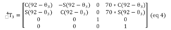
The parameters can be plugged to the standard DH formula below to get the Homogenous Transformation Matrixes (Table 3).
| K | θk | dk | rk | αk |
|---|---|---|---|---|
| 1 | 0 | 0 | 57.35 | 0 |
| 2 | π/2 | 0 | 58.2 | 0 |
| 3 | (θ2-40) | 0 | 70 | 0 |
| 4 | (92-θ3 ) | 0 | 50 | 0 |
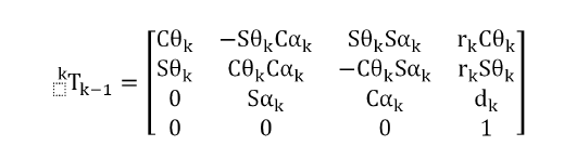
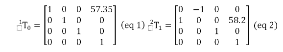
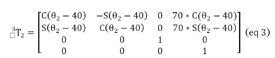
And to find position of the fingertip (P4) with respect to the fixed gripper coordinate frame (P0), the following formula can be applied.
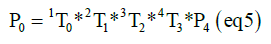
Note that, fixed coordinate system (P0) was taken to be at the centre of the Base (link 1)’s mount hole (e.g., point A (Figure 4). Moreover, P4 is always in the origin of frame 4 (x4,y4,z4); therefore, it can be expressed as follows:
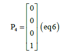
Substituting equation 1-4 and 6 into equation 5 and calculating it would give the position of the fingertip wrt the set fixed coordinate frame. However, the matrixes can also be used to convert rotational velocities and accelerations into the linear velocities and accelerations. Matlab scripts were produced to perform these calculations which are presented in Appendix A.
Static force calculations
As the three fingers are identical, static calculations were also based on a single finger. Note that the static friction between the fingertip and the target object was assumed to be a minimum of 0.5 so that a 1.5 kg object would need a maximum of 30N normal force to be grasped. Doing so would require 10N normal force to be applied by each fingertip. Also, note that the friction between the components of the gripper was neglected throughout the calculations.
Weight analysis and torque spring selection calculations
The Centre of Mass (CM) of each link can be found from the mass properties feature in Solidworks. The joint torque that weight of the links generates can be found by equations 7 and 8:
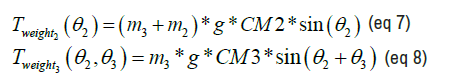
Where: m3 is mass of link 3, m2 is mass of link 2, g is gravity constant, CM2 is centre of mass of link 2, CM3 is center of mass of link 3, θ2 is angular displacement of link 2, θ3 is angular displacement of link 3.
Note that both equations above are a function of joint parameters (e.g., θ2 and θ3). Doing the calculations will allow finding the maximum torque (Tweight-max) that links will experience due to weight and can be used to select torque springs using equation 9.
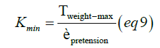
Where: θpretension is the angle to which torque springs are pre-tensioned at the initial position of the gripper and is determined by the CAD model and spring specifications, and Kmin is the spring constant of the torque spring.
Torque required applying 10N
As the joint torque experienced by weight of the links (Tweight) and joint torque exerted by the torque springs (Tspring) are now known variables, calculation of torque needed to be applied on the joints to achieve 10N normal force (T10N) at the fingertip can be calculated using equation 10. Note that link 3 will be held by the stands while the gripper performs grasping action; therefore T10N is not expressed.

Where: Tspring2(θ2)is the joint torque applied by the spring of link 2, μ is friction factor between the target object and fingertip, Fnet is the net force applied to the target object, L3is the length of the link 3.
Note that T10N2 is function of angular position (e.g.,θ2). The Matlab code for calculating torque required to apply 10N fingertip force is given in Appendix B, which also includes the weight analysis and torque spring selection calculations.
String force required to actuate link 2 and link 3
The force required to be applied by the string to achieve the calculated joint torques can be calculated by taking the maximum joint torque required (T10N2max ) and applying equation 11. As the string will always act in the parallel direction to link 2 because it is being constrained by the fixtures to do so, the equation 11 is valid.
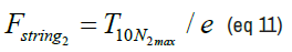
Where: e is the eccentricity of string from the neutral axis of link 2.
Also note that the force on the string is also equal to the force acting on the leadscrew because leadscrew will provide actuation of the string.
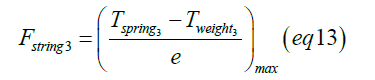
The string actuating link 3 is not directly actuated by the leadscrew but is attached to a stationary point on the base (link 1) such that when link 2 starts rotating; link 3 also starts to rotate. To synchronise the motion of link 3 with link 2, a linear spring must be attached in series to the string of link 3. To calculate the spring coefficient of this linear spring, equation 12 can be used.
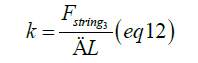
Where the force required from the string ( F string3) can be calculated using equation 13.
And the change in distance of the string (ΔL) when the gripper is operating can be measured in Solidworks.
String stress calculations
To check if the string has enough strength to stand to the tension force induced on it, equation 14 can be used.
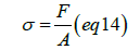
Where: F is the maximum calculated force induced on the selected string and A is the cross-sectional area of the selected string.
Lead screw and motor calculations
The maximum torque required by the motor (Tm) referred to the motor axis, including the efficiency of the leadscrew so that the calculated string forces can be provided, is defined by equation 15. This would allow the selection of a suitable motor and a leadscrew for the system.
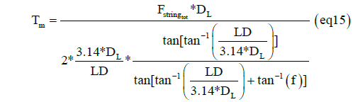
Where: DL is leadscrew diameter, LD is lead, and f is coefficient of friction between leadscrew and nut.
The Matlab code for motor and leadscrew calculations is provided in Appendix C. Note that equation 15 was developed based on calculation methods presented [23,24].
Dynamic force calculations
Dynamic force analysis aims to find the rotational acceleration and velocity of the links and the grasping time of the gripper given the torques acting on the joints. The method to conduct this analysis can be based on extracting all tabulated results from the static force analysis (weight, spring, and the input torque provided by motor) into a spreadsheet and finding the net torque acting on the links. This could then be converted into acceleration using equation 16.
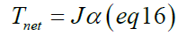
Where the moment of inertias (J) of the links can be measured in Solid works. The input torque by the motor could then be manipulated in the spreadsheet to achieve the set target acceleration of the links. The velocities can be calculated assuming trapezoidal velocity profile using equation 17 and 18.
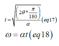
Then, using the forward kinematic calculations that were presented in section 2.3.1, the linear fingertip velocity can be found. Note that the equations used to perform dynamic calculations are based on methods presented by Giorgio [25].
All the results below were obtained using the methods presented in the 2.3.
The joint torque required to apply 10N fingertip force
The result of 2.3.2B is shown in Figure 5. The results indicate that the torque required to be applied on joint 2 varies by the angular position of link 2, where the maximum torque required to be applied is 0.9156Nm and occurs at the final position of link 2.

Figure 5. Matlab plot of torque required to be applied to joint 2 to achieve 10N force at the fingertip.
Dynamic force analysis
As stated in section 2.3.3, the input joint torque provided by the motor and leadscrew was manipulated to achieve desired output velocity of the fingertip, assuming the motor control algorithm can vary the input motor torques to achieve the same calculated input joint torques it shows the results of the dynamic force calculations. As can be seen from Figure 6A, the maximum input joint torque require by the motor is 0.23 Nm. Looking at Figure 6B, the maximum linear acceleration of the fingertip is 70 mm/ s^2. Figure 6C shows the grasping time of the gripper is 2.83s in total, and the maximum linear fingertip velocity the gripper can achieve is 108 mm/s.

Figure 6. Dynamic force analysis results (A) Input joint torques vs. angular position of the link 2. B) Linear acceleration of the fingertip vs time. C) Linear velocity of the fingertip vs. time.
Finite element analysis
The finite element analysis was conducted based on the static and dynamic forces acting on the components. All loads acting on the components were multiplied by a factor of 2 to compensate for a safety factor of 2. The results are shown (Figure 7) and the maximum stress acting on the components is 15.78 MPa.

Figure 7. Results of finite element analysis, A) link 2 force analysis, B) link 3 force analysis, C) base (link 1) weight analysis, D) Base (link 1) force analysis.
Summary of achieved list of target specifications
The summary of achieved list of gripper specifications is presented (Table 4).
Design
During the literature survey, Hou et al. was the only paper found which has conducted research based on integrating UPG and UAG, which used a non-tendon driving mechanism for the integrated gripper. However, in section 1, based on the information obtained from literature review, it was concluded that if the integrated gripper would be designed with tendondriven actuation mechanism, the development and use of complex control algorithms and expensive hardware can be eliminated to achieve grasping stability yet would be highly stable and universal. This implied that the only integrated gripper design presented by Hou et al., can be further improved to be made more “efficient”. When comparing the finalized design to that of Hou et al., despite the driving mechanism, some discrepancy was found. One of the main things that could be seen was that Hou’s design had two fingers, whereas the designed gripper has three fingers. The reason a threefingered gripper was chosen was based on statistical research conducted by Pham and Yeo, who concluded that “A three-fingered gripper can do 90% of the jobs a five-fingered gripper can”, thus designing a three-fingered gripper ensured further universality. However, there were many similarities as well. When analyzing Hou’s paper, one substantial similarity spotted was based on the concept kinematic configuration of the gripper. Even though the kinematic concept configuration of the designed gripper was purely assessed and chosen based on the decision-making matrix, it was found to be precisely the same with Hou’s design, where both designed grippers used two revolute joints per finger. When further analysed, it was found that both designed grippers used pin joint structures as their links as well. This gave further confidence to the design of the gripper and ensured that the developed concept design of the gripper was one of the most suitable and applicable concepts. On the other hand, the design of the UPG fingertip was developed by the concept design provided by Amend et al., with a tiny change made to the external collar, which was designed to be square to fit to the link 3 holding platform. When compared to Hou’s UPG fingertip, no difference could be noted except for the fact that he has also used a round external collar as Amend et al. [26,27].
Target specifications
One of the project's main objectives was to compare the achieved specifications of the designed gripper (Table 4) to the list of target specifications set for the designed gripper (Table 2). Doing so allows achieving the second aim of the project, which is to establish that the designed gripper is operating efficiently.
| Spec name | Spec values | Spec units |
|---|---|---|
| Number of fingers | 3 | (pcs) |
| Actuation approach | DC motors | (no unit) |
| Maximum fingertip speed | 108 | (mm/s) |
| Minimum grasping time | 2.83 | (s) |
| Travel | 0-121.44 | (mm) |
| Gripper weight | 673.36 | (g) |
| Payload | 1.5 | (kg) |
Overall dimensions  represents (friction co-efficient quality) represents (friction co-efficient quality) |
233.07 × 238.92 | (mm) |
| Clamping force of gripper (min) | 30 (assuming contact friction coefficient of min 0.5) | (N) |
Table 4. Achieved list of specifications of the designed gripper.
Design specifications
The only specification that could not be achieved was the target diameter of the gripper, which was targeted to be a maximum of 180 mm but was measured to be 239 mm in the final design. Although this was a big difference, it is not considered a critical one. This is because the maximum range of the angular travel of the fingers, which is adjustable by designing, is the main parameter that influences the maximum diameter of the gripper. However, the maximum range of angular travel also influences the results of linear travel. As the designed gripper achieved a linear travel of 121.48 mm e.g., twice the value of target linear travel, the problem of the gripper's maximum diameter is solvable. This implies that decreasing the maximum angular travel of the fingertip would allow achieving the maximum target diameter of the gripper without affecting the achievement of other target specifications that get affected by this, such as linear travel (Figures 8 and 9).

Figure 8. Design of passive gripper fingertip (A) concept design, (B) final CAD design.

Figure 9. Final design of the gripper, Note that all yellow and white components are 3D printed, all others are off-the-shelf components.
The weight of the gripper was approximately half the maximum set allowable target weight of the gripper of 1 kg. This was achieved by intensive design evaluations taken during the development of the gripper. However, it must be noted that the calculated weight of the gripper was an approximation by Solid works because the weight of some of the off-theshelf components (e.g., leadscrew and nut) was not stated on the website of the suppliers and had to be approximated by assigning material density in Solidworks. Thus, this may have slight effects on the results of dynamic calculations. However, when the simulations were conducted to confirm the results there were less than 1% disagreement between results and simulations. Thus, the effect of this is negligible on calculations.
Force specifications
Force calculations performed mainly focused on calculating the achieved payload of the gripper. As stated in section 2.3.2, assuming a coefficient of static friction of 0.5 acting in the contact region of the gripper and the target object, 10N clamping force per finger would provide a total payload of 1.5 kg. However, it is essential to note that the membrane of UPG, which is in contact with the object being grasped, is made of latex rubber. The coefficient of static friction of 0.5 for latex rubber is a minimum, generally assumed for wet or dusty contacts. Usually, a friction factor up to 1 is applicable to be assumed for dry contacts of latex rubber with various objects, according to Engineering Edge (2021). Thus, this would allow a 30N clamping force to grasp an object weight up to 3 kg. As a safety factor of 2 was applied on the conducted FEA (section 3.4), grasping a 3 kg object would not cause a mechanical failure on the components as well [28].
Although the project mainly focused on analyzing quantitative data of the designed gripper, qualitative data was also considered. The selected tendon for the gripper (Dyneema SK76 made string) had a maximum strain of 2.58%–3.96% occurring at a maximum stress of 3900 MPa (UTS), which increases at a linear trend according to Sanborn et al., This was analyzed to check if it would elastically yield enough to cause desynchronization of motor input speed with fingertip output velocity. The stress calculations based on the methods presented in section 2.3.2D, showed that the stress on the string was 80 times less than the UTS of the selected string, which means the elastic strain of the string was negligible to cause desynchronization. Doing so was particularly important because standard cords made of polyethene or nylon has an elastic strain of over 20%, occurring at 150MPa, according to Lynch and Woodhouse. Thus, these cords can cause high amount of desynchronization [29].
Dynamic specifications
The dynamic force analysis was the final calculation required to complete the full list of achieved specifications. During dynamic force analysis, it was found that an input joint torque of 0.23 N allowed achieving a maximum fingertip acceleration of 70 mm/s^2. Assuming trapezoidal velocity profile, maximum fingertip velocity was calculated to be 108 mm/s which is twice higher than the minimum set target velocity. However, it should be noted that the motor was selected based on force calculations on section 3.1 and can provide a maximum input joint torque of 0.92 Nm. This implies that the input joint torque can be increased more than four times for dynamic analysis, and significantly higher fingertip velocities can be achieved. However, doing so is not recommended as long as dynamic vibration calculations are conducted. This is because high velocities cause a high amount of vibrations, increasing the likelihood of vibrations causing either dynamic destabilization or self-destruction of the gripper. Increasing fingertip velocity would decrease the grasping time as well, but the grasping time was in the range of maximum target grasping time of 5 seconds; thus, increasing fingertip velocities was not seen as a need in the scope of this project.
Finite element analysis
The third important aim of the project was to ensure that none of the designed components fails due to the mechanical loads acting on them by conducting FEA. All analyzed components were made of ABS, and according to Dielectric Manufacturing, the yield stress of ABS is 40 MPa. Thus, none of the FEA results (presented in section 3.4) showed plastic yielding of ABS. The highest stress out of conducted 4 FEA was found to be on base (link 1) force analysis which had a maximum stress of 15.78 MPa, more than twice below the yield stress of ABS. Considering a safety factor of 2 was applied to all the forces during the FEA, these results are astonishing. Thus, success was achieved [30,31].
In this paper, the design of a three-fingered tendon-driven integrated gripper, based on integrating UAG with UPG to achieve variable stiffness soft fingertips, is presented. Extensive research is done to understand the working principle of both gripper types. Method of design is presented and modelled in Solidworks. The designed gripper is compared to the only design presented for integrated gripper: Hou et al. (2018)’s design. One fundamental similarity noted is based on both designs adopting the same kinematic configuration for the gripper. Thus, it can be concluded that, optimal development of the designed gripper was achieved.
To ensure operating efficiency of the designed gripper, the objective set is to theoretically compare the specifications of the designed gripper to those of other available grippers. Target specifications were set based on analysing specifications of four commercial non-tendon-driven grippers. Method of kinematic, dynamic and force analysis is explained which was then used to calculate the achieved list of target specifications of the designed gripper. The results show that the only specification not met is the diameter of the designed gripper, which was relatively larger than most of the analysed commercial grippers. However, it was discussed that it can be easily fixed if small design changes are made on the stands of the gripper. A fingertip velocity of 70 mm/s is achieved, which is above the set target velocity; however, it is concluded that it can be increased by four times if dynamic vibration analysis is conducted. The selected tendon for the designed gripper has negligible elastic yielding; thus, full synchronisation of the input motor speed with the output fingertip velocity is noted. This fact ensures that when the designed gripper is actuated by the motor, it will operate precisely and accurately. As the static coefficient of friction between the target object and the fingertip is underestimated by half amount during the calculations, to compensate for wet and dry surfaces, the designed gripper was argued to grasp twice the calculated payload of 1.5 kg.
Furthermore, FEA is conducted for the three primary designed components of the gripper; all designed to be made of ABS, to ensure they will not fail due to mechanical loads acting on them.
Overall, all project aims and objectives are achieved, and it is theoretically established that the designed gripper is efficient. This implies that, theoretically, the designed gripper requires a simpler control algorithm, operates at a high performance, and is highly universal. Nevertheless, four future work recommendations are given to experimentally establishing the efficiency of the designed gripper.
All the project aims, and objectives were achieved with high quality. It was theoretically established that the tendon-driven integrated gripper is an efficient design approach to the grippers. This indicates that the methodology section was well thought and written and that exclusively gathered results firmly obey the methods demonstrated in the methodology section. To make the methodology section re-usable in future improvements, various engineering tools such as Matlab scripts for performed calculations were developed and used throughout the project. For further improvements on the idea, some future work recommendations can be suggested:
→ Make slight changes in the design of link 2 and link 3 stands to decrease the angular travel of fingers so that the maximum target diameter of the gripper can be met.
→ Conduct dynamic vibration analysis for the designed gripper with the aim of increasing the fingertip velocity. This would reduce the operation time of the gripper; thus, the designed gripper can be used with high-speed robots such as delta robots.
→ Develop a control algorithm for the designed gripper. This can aim to illustrate the ease of control algorithm required for the designed gripper. Doing so will also be a step towards building the designed gripper.
→ Build the designed gripper and conduct various experiments to practically compare the built gripper with that of Hou et al. Doing so would aim to experimentally confirm that the tendon-driven mechanism for the integrated gripper is simpler to build and control, yet equally universal wrt the non-tendon-driven integrated gripper(s). Besides, the positive effect of achieving variable stiffness fingertips can also be confirmed by being experimented with and compared to Qiao et al. paper.
The research work was carried out under the supervision of Dr. Xin Dong as a thesis submission to Department of Mechanical, Materials and Manufacturing Engineering, University of Nottingham, University Park, Nottingham NG7 2RD, UK
Mahmud Huseynov was born and raised in capital city of Azerbaijan, Baku, where he had his high-school education. During school years, he was always noticed by his teachers of mathematics and science departments. Later he has moved to UK, to continue his university studies. He has got an offer from University of Nottingham for bachelor Mechanical Engineering course and graduated with top 1 student award (2021). Besides, he is interested in neuroscience, artificial intelligence, and robotics. Mahmud now has got an offer from University College London to do his master’s degree in the field of robotics and AI.
This research did not receive any specific grant from funding agencies in public, commercial or non-for-profit sectors.
The author declares no competing financial interests
Not applicable
Not applicable.
Advances in Robotics & Automation received 1275 citations as per Google Scholar report