Review Article - (2022) Volume 13, Issue 1
Received: 28-Jul-2021, Manuscript No. gjto-21-38111;
Editor assigned: 30-Jul-2021, Pre QC No. P-38111;
Reviewed: 13-Jan-2022, QC No. Q-38111;
Revised: 18-Jan-2022, Manuscript No. R-38111;
Published:
23-Jan-2022
, DOI: 10.37421/2229-8711.2022.13.274
Citation: Chourasia, Ramesh Chandra, Navneet Verma, Puranjan Singh and Shashi Kant. “Speed Control of DC Motor using PID Controller.” Global J Technol Optim 13 (2022): 274.
Copyright: © 2022 Verma N, et al. This is an open-access article distributed under the terms of the Creative Commons Attribution License, which permits unrestricted use, distribution, and reproduction in any medium, provided the original author and source are credited.
The purpose of this paper is to design a speed controller for a dc car. DC car is widely used in various applications, such as cranes, milling machines, elevators, lathe machines, blowers, fans, drilling rigs, etc. This paper proposes the construction of a PID controller and the selection of PID control parameters. Here, the PID controller is used to control the speed of the DC vehicle and to simulate and calculate MATLAB is used. The selection of PID parameters is indicated by several ongoing tests and the PID parameter setting method is discussed.
Milling machines • PID • MATLAB • Horsepower
The PID (Proportional-Integral-derivative) controller is a well-known controller for its simple and powerful operation in a wide range of operating conditions. The design of such a control that requires the specification of three parameters for a limited time, a limited time period and a time from the other [1]. Setting the PID parameter is called tuning. PID control adjustment using a variety of methods. In the Ziegler Nicholas Tuning method, the integrated and derivative method is maintained consistently, the constant equivalent of the various simulations of the performance of your identity in this method was Parliament overshoot and time Ts defined. The genetic algorithm is repeated several times until the best values come from Mp and Ts. There are three categories in this algorithm, namely selection, crossover and genetic modification. PID controller parameters kp, ki and kd can be controlled to generate various response curves from a given process [2].
The DC motor model
A DC motor is any of a class of rotary electrical motors that converts direct current electrical energy into mechanical energy. It is used for a wide variety of industrial, commercial and residential operations [3].
Figure 1 shows the connection of the shunt car type dc. It consists of a shunt field connected similarly to the armature. The shunt field curve is constructed with several turns of a small gauge fence and has a low current flow and very high compared to a series fence field. Therefore, these types of motors have excellent speed and position control. These motors are therefore widely used in applications that require five or more horsepower. The Figure 2 describes the dynamic performance of a DC car based on a scheme diagram.

Figure 1. Daigram of DC shunt motor.

Figure 2. The schematic diagram of DC motor.
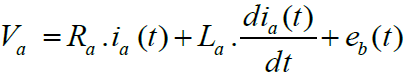 (1)
(1)
eb (t) = kb . w(t) (2)
Tm (t) = KT . ia (t) (3)
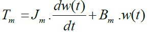 (4)
(4)
Then ,
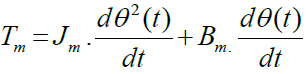 (5)
(5)
Now, the transfer function will become:

Where,
Va = armature voltage (V) Ra = armature resistance
La = armature inductance (H) Ta = armature current (A)
Eb = back emf ω = angular speed
The DC motor under study has the following specifications and parameters (Table 1).
| Parameters | Value |
|---|---|
| Armature inductance (Henry) | La = 0.1215H |
| Armature resistance (ohm) | Ra = 11.2Ω |
| Rotor inertia (kg m2 ) | Jm = 0.002953Nms/rad |
| Armature Voltage (Volt) | Va(t) = 240V |
| Viscous friction coefficient (Nms/rad) | Bm = 0.002953Nms/rad |
| Motor Torque constant (Nm/A) | Km = 1.28Nm/A |
| Back emf constant (V s/rad) | Kb = 1.28Vs/rad |
| Speed | W = 1500rpm |
Simulink modeling of DC motor: Simulink modeling of DC motor was shown in Figure 3.

Figure 3. Simulink modelling of DC motor.
Tuining of PID controller using different methods
Ziegler-Nichols tuning method: The Ziegler-Nichols Act is a PID amendment law that seeks to produce fair values for the three parameters of obtaining a PID:
Kp - is the advantage of the control system
Ti - is the integration time of the controller
Td - is the time from the controller
Given the two parameters for measuring the measured response obtained from the ratings:
• Tu time of oscillation frequency at the intensity level
• The margin gain loop stability
For the purpose of obtaining good regulation (refusal to be disturbed):
Ziegler-Nichols law considers that the system has a transfer function of the following form:

The model is similar to the system response to 0 waves and the stability limit, with everything else almost done below. If the actual system is straightforward, looks isolated and lazy, it does not make much difference that the model is fake, and the results are good enough.
The necessary steps for this approach are:
1. The combined and derived coefficient must be zero.
2. The corresponding coefficient increases gradually from zero until the system begins to flow continuously. At this point, a coefficient equal to it is called the maximum gain (Ku) and the downtime is called the end time (Tu) (Table 2).
| Controller type | PID |
|---|---|
| Kp | Ku/1.7 |
| Ki | Tu/2 |
| Kd | Tu/8 |
If we choose the classical Ziegler-Nichols tuning rule, we can determine that the PID gains should be:
Loop gain Kp = 0.6 * Ku = 6.7
Integral time constant Ti = 0.5 * Tu = 0.033
Derivative time constant Td = 0.125 * Tu = .0083
Effects of increasing the parameters of PID controller
From the Table 3, we can examine the following parameters:
1. Maximum overshoot (Mp)
2. Setting time (Ts)
| Parameter | Rise time | Overshoot | Setting time | Steady-state error | Stability |
|---|---|---|---|---|---|
| Kp | Decrease | Increase | Small change | Decrease | Degrade |
| Ki | Decrease | Increase | Increase | Eliminate | Degrade |
| Kd | Minor change | Decrease | Decrease | No effect in theory | Improve if Kd small |
The maximum overshoot of the system is approximately 47.4% and the setting time is in relation to 0.837 sec.
The Figure 4 shows the DC motor speed with PID tuining using Zieglernicholas method [4,5].

Figure 4. Speed response with PID controller using fixed set point.
Genetic algorithm method
Genetic algorithm is a random search method that can be used to solve incompatible mathematical systems and improve complex problems. GA uses the rules of possible modification instead of determining the rules and regulates the number of possible solutions known as human or chromosomes that change in sequence. Each duplication of the algorithm is called a generation. The emergence of solutions is done through solid work with genetic suppliers such as reproduction, crossover, and genetic modification. The genetic algorithm as shown in Figure 5 usually starts with a random number. This number (mating lake) is represented by a truly equal number or two-dimensional series called a chromosome. Personal performance is measured and evaluated by purposeful work, which gives each person a corresponding number called their suitability [6,7]. The proposed PID controller with applying Genetic Algorithm Method is given in Figure 6, and also the genetic algorithm gain values for the tuning is given below in Table 4.

Figure 5. Genetic algorithm method.

Figure 6. Response of genetic algorithm based PID controller.
| Gain Parameters | Gain values |
|---|---|
| Kp | 19.88 |
| Ki | 0.1376 |
| Kd | 0.5578 |
The range of Kp, ki and Kd is taken in between (0-100) KP Ki and Kd values are divided by purpose function on Table 5. Figure 7 shows the variation of the best order at the time and the best order is given as the one that gives the zero and the fixed position error, the zero time and the setting time. With a well-planned system throughout the season to the most appropriate level of debt conversion has given us the states of honorable electoral strategies in a particular election-electing organization with elitism.
| Parameters | Turning Method | |
|---|---|---|
| Conventional PID | Genetic Algorithm | |
| IAE | ||
| KP | 14.7312 | 5.0916 |
| KI | 105.15 | 80.8051 |
| KD | 0.547 | 0.0549 |
| Rise time(sec) | 0.00622 | 0.0763 |
| Settling time(sec) | 0.0837 | 0.116 |
| Overshoot(%) | 47.4% | 0% |
| Peak | 1.41 | 1.02 |

Figure 7. Step input of controlled DC motor drive system.
Applications
• Electric bikes
• Electric trains
• Robotic control
• Swing machine
• Drill machines
Obviously the PID controller doesn't get the desired result. A good PID control calculation setting is shown. The positive result of a closed circle is displayed. This paper Demonstrates strategies to plan speed control for DC vehicles with the use of GA and to improve using GA and to resolve over time and fixed condition error. The end result is further shown to make and reflect an increase in GA.
Global Journal of Technology and Optimization received 847 citations as per Google Scholar report