Research Article - (2022) Volume 12, Issue 3
Received: 21-Feb-2022, Manuscript No. jcde-22-55136;
Editor assigned: 24-Feb-2022, Pre QC No. P-55136;
Reviewed: 16-Mar-2022, QC No. Q-55136;
Revised: 23-Mar-2022, Manuscript No. R-55136;
Published:
30-Mar-2022
, DOI: 10.37421/2155-9821.2022.12.439
Citation: Kassa, Alula A, Asgedom, Asmare Mesfin and Amare Gebremedhin. “Dynamic Compaction of Backfills and its Dynamic Load Effect on Underlying Concrete Pipe.” J Civil Environ Eng 12 (2022): 439.
Copyright: © 2022 Kassa AA, et al. This is an open-access article distributed under the terms of the Creative Commons Attribution License, which permits unrestricted use, distribution, and reproduction in any medium, provided the original author and source are credited.
Sources of funding : None
In this study, the effect of dynamic vibrational compaction loads on the stability of underlying concrete pipes using finite element modeling (FEM) analysis method is investigated. The FEM is conducted on different reinforced concrete pipe (RCP) classes with variable diameters. And different parameters include; increasing backfill heights above the pipe crown, geometry related material properties, and compaction load locations are considered in the modeling. ABAQUS three- dimensional FEM is used in modeling of RCP and surrounding soils under the action of dynamic vibrational compaction loads. The FEM loads acting on the pipe walls are correlated with loads specified in ASTM C-76 resulted by Three End Bearing (TEB) experimental test known as D-load test. Therefore, the backfill height at which FEM loads equals with the TEB loads that cause 0.25 mm crack on the RCP is the critical fill depth in dynamic vibrational compaction of trench embankment.
Soil Compaction • Modeling • ABAQUS FEM • Compaction load • D-Load
Construction loads are an important but often overlooked factor in underground pipe design and installation. Common compaction equipment’s used in road embankment construction can be a major contributor to buried pipe damages. During the construction of backfill embankment, compaction of backfill materials has carried out through vibrated compactors. While times, a high cycling loads are transfer to the bottom and might cause severe damage to the burred pipelines. Many researchers are argued that, the effects of vibratory compaction on stability of substructure utilities are significant especially to pipelines. The possible failures of buried concrete pipes are due to excess vibrations loads induced from the vibratory equipment and due to uncertainties for the required lift thickness to dissipate the compaction loads [1]. Therefore, this research is aimed to investigate the effect of dynamic vibrational loads induced during compaction on concrete pipes and safe backfill soil depth in having stable underlying concrete pipe is determined.
To analysis the compaction load effect on buried concrete pipes, various variable parameters; vibratory roller loading conditions, concrete pipe geometry, soil layer material properties, backfill soil thickness and other related parameters have studied. Besides, the effect of boundary conditions, buried concrete pipe modeling, roller-soil system modeling is considered. In investigating the acting stresses on pipe walls, ABAQUS 3D FEM software is used in modeling of RCP and surrounding soils under the action of dynamic vibrational compaction loads. The interaction in between concrete pipe with soil, the contact with soil layers and roller soil contact are considered using a contact modeling in ABAQUS software. In understanding the effect of compaction loads on buried CP, the TEB test results specified in ASTM C-76 is used for correlation of the FEM results. In this section, previous research works related to dynamics compaction of soil, analysis and design methods of concrete pipe, models of vibratory drum - soil system and for numerical result correlations, Three-Edge-bearing D-load test experimental results are reviewed and discussed.
Construction loads
The construction load from the compaction machine is applied to the pipe as a non-uniformly distributed external pressure. The pipe derives its support from distributed external earth pressure around the lower portion of its circumference. The pressure distribution, transferred via the surrounding soil, significantly influences the pipe’s stiffness. The applied earth pressure has a normal component and a traction component, resulting from friction between soil and concrete. As shown in Figure 1, the combined effects of moment (M) and thrust (N) at the sections of maximum flexural stress produce the tension on the inside of the pipe and compression on the outside of the pipe at crown and invert. In contrary, at spring line, the tension and compression occur on the outside and inside of the pipe, respectively [2].

Figure 1. Moment and thrust induced on a buried pipe. (W. V. Ping, P.E., et al., 2001).
Selection of pipe strength
The ASTM Standard C76 for reinforced concrete culvert, storm drain and sewer pipe specifies strength classes based on the D-load at 0.25 mm crack and/or ultimate load. For reinforced circular pipe, the three-edge-bearing test load equals the D-load × the inside diameter [3]. The required three-edgebearing strength for circular reinforced concrete pipe is expressed in terms of the D-load and is computed by the equation:
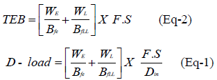
Where,
WE =Total Earth Load,
WL = Total Live Load,
Din = Internal Pipe Diameter
Bfe = Embankment Bedding Factor, (Table 1)
BfLL = Live Load Bedding Factor, (Table 2) and
F.S = Factor of Safety
| Pipe Inside | InstallationType | |
|---|---|---|
| Diameter (in) | Treated | Untreated |
| 12 | 2.5 | 1.7 |
| 24 | 2.4 | 1.7 |
| 36 | 2.3 | 1.7 |
| 72 | 2.2 | 1.7 |
| 144 | 2.2 | 1.7 |
| Fill heights | Pipe diameter, (in) | ||||
|---|---|---|---|---|---|
| (ft) | 12 | 24 | 36 | 72 | 144 |
| 1 | 2.2 | 2.2 | 1.7 | 1.3 | 1.1 |
| 2 | 2.2 | 2.2 | 2.2 | 1.5 | 1.3 |
| 4 | 2.2 | 2.2 | 2.2 | 2.2 | 1.5 |
| 6 | 2.2 | 2.2 | 2.2 | 2.0 | 2.0 |
Models on Vibratory Drum - Soil System
Throughout the normal operations of vibratory roller, the soil produces elastic-plastic deformation under the combined action of dynamic and static load, which shows that the stress-strain relationship is nonlinear and timedelay. Too effectively capture this complex behavior, the use of discretized numerical approaches is required [4].
Previous finite element (FE) models have been developed for the drumsoil system, but these focus on the effects of drum excitation amplitude, homogeneous response or inversion methods. The aforementioned models either modeled the soil as a perfectly elastic or elasto-plastic medium with no damping, or used numerical Rayleigh damping to approximate system energy loss. Rayleigh damping, however, does not explicitly represent materialbased damping properties and is used purely for mathematical convenience in approximating observed energy loss in a system. As a result, these previous models were unable to explicitly model individual material dissipation properties [5-7].
The previous works related to compaction theory, models on vibratory drum - Soil system, analysis and design methods of buried concrete pipes, and effect of dynamic vibration compaction load on buried concrete pipe are reviewed. And the source of the material parameters and loading conditions implemented in the finite element model is taken from experimental models published in the literature and taken from recognized standards. The results of these experiments of previous researches are employed for the purpose of verification of the results of this specific research.
To study the dynamic vibrational compaction load effect underlying concrete pipe using the finite element software package ABAQUS, different material characteristics and several parameters; concrete pipe sizes, soil material properties, backfilling lift thickness and compaction load locations (backfill compaction load location state, BCS) and side-fill compaction load location state, SCS) are considered. The Mohr Coulomb plasticity model is used for analysis applications in the surrounding soil zone and Concrete Damage Plasticity model is used in modeling of concrete pipes [8,9]. The maximum numerical loads acting on underlying concrete pipe under the action of dynamic vibrational load passing through different backfill soil layers are correlated with loads causes 0.25 mm cracks specified in ATM C-76 standards. Finally, the allowable backfill soil layer heights during compaction process of trench embankment are determined.
Finite Element Modeling Of Pipe-Soil Compaction
In this study, finite element models of the pipeline and soil are established using the package ABAQUS to carry out stress analysis on buried pipeline caused by static and dynamic compaction loads. In order to perform this analysis for a buried concrete pipeline, it is necessary to accept the assumptions such that, the joint between pipeline segments is not considered, the soil is elasto-plastic characterized by Mohr Coulomb theory and the static and dynamic compaction load from the roller comes from road embankment construction.
Finite Element Modeling
The Finite Element Model contains three main parts: roller drum, pipeline and surrounding soils. All element types included the first-order hexahedral element, triangular prism element (C3D6) and (S4R) for modelling of roller drum. The optimum mesh with regard to element type is selected by the convergence of analysis results. The pipe-soil interface, modelled by using surface-to-surface method, allowed the stress transferred between contacting surfaces. The surrounding soil model is partitioned into specific zones so that the related properties are distinguished. Rayleigh damping parameters (α and β, units of sec-1 and sec, respectively) are used to numerically approximate material damping in the FE model and constant for all soil types used in this analysis. The Mohr-Coulomb plasticity model is used for analysis applications in the surrounding soil zone [6,9,10].
The boundary conditions are used to simulate the actual constraints that represent the effect of the surrounding soil in the trench installation. When the roller is moving on the backfill, there are no responses at infinity. Therefore, the roller support in vertical direction is applied at the four sides of a trench wall. The translation degree of freedom is constrained at the bottom of the bedding zone. In this case, every node above the bottom of the bedding zone can be freely displaced downward in vertical direction (Y-direction). The interaction between pipe and soil surface consists of two force components. One is perpendicular to the interaction surface, which is the normal behaviour, and the other one, tangent to the surface, which is the tangential behaviour and consists of sliding between two surfaces and possibly frictional shear stresses [11].
It is assumed that the tangential contact property between the concrete pipe and soil structure is penalty contact with full friction and the normal contact property is modelled as hard contact. The interaction between the vibratory drum and soil during the vibratory compaction process is modelled as tangential contact property by assuming the soil is an elasto plastic with certain stiffness and damping, the vibratory drum is considered as analysis object and its quality (including frame) M, the stiffness k and the damping c of soil considered as the parameters of “vibratory drum – soil” equivalent dynamics model and the vibratory drum keeps close contact with the soil during all the vibratory compaction process. And the FE-Time model uses an explicit timeintegration approach, where contact between the drum and soil is explicitly modelled using a penalty contact algorithm.
Parametric Study
The parametric studies of pipe-soil compaction model in Figure 2 execute the analysis with different sets of input parameters included with the pipe sizes, backfill material, backfill heights, side-fill materials, and loading locations on the RC pipeline compaction process as shown in Table 3. For all analysis cases, bedding thickness is 15 cm and its soil type is sandy silt (Si85).

Figure 2. Geometric dimensions of a trench installation FEM model. (American Concrete Pipe 4 Association, 2000).
| Pipe Diameter | Soil Type and Backfill Height | Side-fill Material | Loading Locations |
|---|---|---|---|
| 61 cm | 15 cm with Si85 (sandy silt) | ||
| 30 cm with Si85 (sandy silt) | sandy silt | Backfill compaction (L1) | |
| 45 cm with Sn90 (gravelly sand) | (Si85/Si85) | ||
| 60 cm with Sn90 (gravelly sand) | Side fill compaction (L2) | ||
| 91 cm | 15 cm with Si85 (sandy silt) | ||
| 30 cm with Si85 (sandy silt) | sandy silt | Backfill compaction (L1) | |
| 45 cm with Sn90 (gravelly sand) | (Si85/Si85) | ||
| 60 cm with Sn90 (gravelly sand) | |||
| 1.22 m | 15 cm with Si85 (sandy silt) | ||
| 30 cm with Si85 (sandy silt) | sandy silt | Backfill compaction (L1) | |
| 45 cm with Sn90 (gravelly sand) | (Si85/Si85) | ||
| 60 cm with Sn90 (gravelly sand) | Side fill compaction (L2) | ||
| 1.37 m | 15 cm with Si85 (sandy silt) | ||
| 30 cm with Si85 (sandy silt) | sandy silt | Backfill compaction (L1) | |
| 45 cm with Sn90 (gravelly sand) | (Si85/Si85) | ||
| 60 cm with Sn90 (gravelly sand) | Side fill compaction (L2) |
The effect of compacting locations on the behavior of buried pipes is evaluated. To indicate the most critical zone, the dynamic force was applied at two different locations: L1 and L2 as shown in Figure 3. L1 is the backfill compaction simulated at a pipe’s middle span and L2 is the side fills compaction simulated on pipe’s side span. All load locations are applied in transversal directions [7].

Figure 3. Backfill load location (L-1) and Side fill load location (L-2).
The dynamic forces from SV510D roller compactor machine including with the weight of roller is used in the FEM compaction model. The drum of the vibratory drum is modeled as a rigid body cylinder. A static load equal to the combined weight of drum and frame) is applied to the center of the drum. Excitation force is created by uni-directional or counter-rotating eccentric masses, m0, located at effective moment arms of e0 within the drum (Figure 4); magnitudes of eccentric mass moment, m0e0, can range from 0 to 5.0 kg-m, and excitation frequencies, Ω=2πf, can range from 20–35 Hz. These parameters are derived from a Sakai SV510D. The drum-soil contact force, Fc, is then determined using force equilibrium [5,7].

Where, Zd =drum acceleration

Figure 4. (a) Free body diagram of vertical forces acting on drum. (b) Contact force vs. drum 11 displacement response and resulting dynamic stiffness measures (Kenneally, et al., 2015) & 12 (Anderegg & Kaufmann, 2004) [ 5,7].
The pipe-soil compaction FEM model is created such that several interesting parameters can be varied and investigated. The analysis is performed in two steps: first the static weight of the drum is applied; and second the dynamic excitation load with the frequency is applied. The vertical harmonic excitation force from the roller is simulated within the normalized amplitude. Moreover, the static load, the load which is the combined weight of drum and frame is simulated as ramp condition.
Control Loads of RCP Experimental D-Load Test Result
To understand the effect of compaction load on a buried concrete pipe and to understand the significance of backfill soil depth in dissipating the compaction stresses, a Three-Edge Bearing experimental D-Load test results recommended by ASTM C-76 is used to compare the FEM result loads. Three Edge Bearing test is a standard test, developed for concrete pipe design (indirect design) and evaluation of structural behavior (ASTM C76 - 15, 2015).
The (ASTM C76 - 15, 2015) standards for reinforced concrete culvert, storm drain and sewer pipe specifies, the strength classes based on the D-load at 0.25 mm crack and/or ultimate loads. The 0.25 mm crack D-load (D0.25) is the maximum three-edge-bearing test load supported by a concrete pipe before a crack occurs having a width of 0.25mm measured at close intervals. Those experimental loads controlled the FEM numerical loads in identifying the safe backfill height in dynamic vibrational compaction of concrete pipe trench embankment. The extracted TEB 0.25 mm values of different RCP class from D-Load experimental results in ASTM C-76 Standard Specification for Reinforced Concrete Culvert, Storm Drain, and Sewer Pipe are shown in Figure 5.

Figure 5. TEB0.25 mm load from ASTM strength test requirements for RCP of different classes.
In this discussion part, the FEA is interpreted in-terms of the compaction load effect on buried pipes, under the backfill compaction state (BCS) and side fill compaction state (SCS). The results are shown in the form of the maximum stresses on concrete pipe versus backfill heights, and pipe diameters. Finally, the maximum load on each backfill depth is correlated with loads resulted by Three-Edge- bearing experimental D-load test that caused cracking of concrete pipe, and for each pipe diameter the D-load test gives loads at the state of 0.25mm crack “TEB0.25 mm”. And from ASTM C-76 Standard Specification for Reinforced Concrete Culvert, Storm Drain, and Sewer Pipe, the TEB experimental D-Load test results is interpreted the FEM results.
Total stresses on RCP in backfill compaction state (BCS)
The total stresses from the compaction loads are the combination of earth stress, static stress and peak dynamic stresses. Generally, in BCS as shown in Figures 6 and 7), the maximum total stresses induced at the pipe crown are higher than induced at the pipe spring line. As the pipe diameter increased, the total stresses are increased, and this increment stresses are resulted from the earth stresses. However, the total stresses at pipe spring line are decreased as pipe diameters increased.

Figure 6. Total stresses in BC state at pipe crown.

Figure 7. Total stresses in BC State at pipe spring line.
As shown in Figure 6 increasing of 15 cm backfill height to the first 15 cm soil layer (15 cm to 30 cm), the total stresses on a pipe crown are decreased by 52%. Increasing of 15 cm backfill height to the second 30cm soil layer (30 cm-45 cm), the total stresses on a pipe crown are decreased by 42%. And further increasing of 15cm backfill height to the third 45 cm soil layer, the total stresses on a pipe crown are decreased by 35%.
Total Stresses on RCP in Side-fill Compaction State (SCS)
Generally, in SC sate, the total stress distribution on different pipe diameters has different stress characteristics. This nonlinear stress distribution is happening due to nonlinear acting of stress from earth stresses on pipe wall, static and dynamic stresses at pipe spring line. In SC location state, the total stresses acting on pipe wall are shown as shown in Figures 8 and 9.

Figure 8. Total stresses in SC State at pipe crown.

Figure 9. Total stresses in SC State at pipe spring line.
Effect of backfill height on RCP compaction of trench embankment
The compaction load acting on backfill soils results in transferring of loads to buried RCP. Those maximum loads acting on RCP analyzed from FEM are compared with TEB0.25 mm D-load standards specified in ASTM C-76 Standard Specification for Reinforced Concrete Culvert, Storm Drain, and Sewer Pipe. Therefore, the backfill lift height that made the FEM load equals with TEB0.25 mm loads caused crack on the reinforced concrete pipe is the critical fill height in RCP compaction of trench embankment.
The loads acting at pipe crown is used to compare with the D-load from standards. This is because the D-Load testing processes have conducted in pipe specimen that uniformly placed on the two bearing strips. When the adjustment of pipe’s position is completed, the upper bearing strip is firmly placed on the top (crown) of the pipe. Finally, D-load test loads at the state of 0.25 mm crack “P0.25” and the state of ultimate strength “Pult” is determined. So that, all D-loads specified on ASTM C-76 were acting on pipe crown (ASTM C76 - 15, 2015). In order to correlate the FEM numerical results with the TEB results, vertical force acting on a pipe wall is extracted from the ABAQUS and the force is divided by the pipe diameter in order to convert it to D-load.
Maximum FEM loads in backfill compaction state at pipe crown
In Figure 10 the combination of TEB0.25 mm loads specified in (ASTM C76 - 15, 2015) and FEM load are presented for comparison. Generally, during the BC state, the maximum FEM loads were increased as pipe diameters increased.

Figure 10. Comparisons of Maximum FEM loads and TEB0.25mm Loads in BC State.
General summery of safe backfill lift thickness in RCP compaction of trench embankment are summarized in Table 4. The safe backfill height for parameters, not specified in Table 4 is recommended to calculate using interpolation form the Figure 10.
| RCP class | RCP diameter | Backfill Height | |||
|---|---|---|---|---|---|
| 15 cm | 30 cm | 45 cm | 60 cm | ||
| Class II | 61 cm | Not Safe | Not Safe | Not Safe | Safe |
| 91 cm | Not Safe | Not Safe | Not Safe | Safe | |
| 1.22 m | Not Safe | Not Safe | Not Safe | Safe | |
| 1.37 m | Not Safe | Not Safe | Not Safe | Safe | |
| Class III | 61 cm | Not Safe | Not Safe | Not Safe | Safe |
| 91 cm | Not Safe | Not Safe | Not Safe | Safe | |
| 1.22 m | Not Safe | Not Safe | Not Safe | Safe | |
| 1.37 m | Not Safe | Not Safe | Not Safe | Safe | |
| Class IV | 61 cm | Not Safe | Not Safe | Not Safe | Safe |
| 91 cm | Not Safe | Not Safe | Not Safe | Safe | |
| 1.22 m | Not Safe | Not Safe | Safe | Safe | |
| 1.37 m | Not Safe | Not Safe | Safe | Safe | |
| Class V | 61 cm | Not Safe | Not Safe | Safe | Safe |
| 91 cm | Not Safe | Not Safe | Safe | Safe | |
| 1.22 m | Not Safe | Safe | Safe | Safe | |
| 1.37 m | Not Safe | Safe | Safe | Safe | |
Maximum FEM loads in Side-fill Compaction state at pipe crown
In comparison of FEM loads of side fill compaction state (Figure 11) and crown. So that, the compaction loads SC sate can have greater effect in pipe lateral movement.

Figure 11. Maximum FEM loads in SC state at pipe crown.
Depending on the depth of backfill cover above the pipe, this study shows under backfill compaction location state (BCS), the compaction loads have significant effect on buried concrete pipe cracking failures. For large RCP diameters of class V, 30 cm backfill height is the critical fill depth in dynamic vibrational compaction of trench embankment. For large RCP diameter of class IV, 45 cm backfill height is the critical fill depth in dynamic vibrational compaction of trench embankment. And in all RCP diameters, 60 cm backfill height is the safe fill depth in dynamic vibrational compaction of trench embankment. Increasing of pipe diameters has small effect on increasing the total compaction stresses on pipe crown.
Under side fill compaction location state (SCS), 15 cm backfill height is the safe fill depth and the dynamic vibrational compaction has no cracking failure effect in all RCP. However, in larger concrete pipe the stresses on pipe spring line are higher than in pipe crown, under side fill compaction state compaction load can cause lateral movement of a pipe. Generally, the higher the backfill soil, the more alleviation in the effect of compacting force, and the less crack occurred on the pipe wall.
The authors wish to express their gratitude to Ethiopian road authority and Mekelle university school of civil engineering for financing this research.
All input data, models, or code generated or used during the study are available from the corresponding author by request. Data can be accessed and reused upon the approval of the first or corresponding author.
List of available data
• Soil strength material properties
• Pipe properties
• Model formulated
• FEM results
Google Scholar, Crossref, Indexed at
Google Scholar, Crossref, Indexed at
Google Scholar, Crossref, Indexed at
Google Scholar, Crossref, Indexed at
Google Scholar, Crossref, Indexed at
Google Scholar, Crossref, Indexed at
Google Scholar, Crossref, Indexed at
Google Scholar, Crossref, Indexed at
Journal of Civil and Environmental Engineering received 1798 citations as per Google Scholar report


