Research Article - (2019) Volume 9, Issue 1
Received: 07-Jan-2019
Published:
16-Feb-2019
Citation: Xikui LV, Tiancheng Z, Bin HE (2019) The Study on Three-Dimensional
Modeling Method of Urban Rail Transit Tunnel. J Civil Environ Eng 9: 328. doi:
10.4172/2165-784X.1000328
Copyright: © 2019 Xikui LV, et al. This is an open-access article distributed under
the terms of the Creative Commons Attribution License, which permits unrestricted
use, distribution, and reproduction in any medium, provided the original author and
source are credited.
The urban rail transit tunnel has many forms, such as single hole single line, single hole double line, parallel and non - parallel, intersection and separation, etc., The modeling is more complicated, the existing 3D modeling method of simple tunnel cannot meet this complexity requirement. According to the actual situation of urban rail transit tunnel, the paper defines the data structure of tunnel modeling, and puts forward the three-dimensional coordinate calculation method of different tunnel forms. According to the actual situation of urban rail transit tunnel, the paper defines the data structure of tunnel modeling, puts forward three-dimensional coordinate calculation method of different tunnel form, and realizes the 3d rapid modeling of urban rail transit tunnel, which meets the multiple modeling requirements of the tunnel.
Urban rail transit; Three-dimensional modeling of tunnel; Three-dimensional design; Visualization
Three-dimensional modeling of tunnel is an important part of 3D design and landscape simulation of urban rail transit lines. For the three-dimensional modeling of the tunnel, many scholars have studied and obtained more research results [1,2] established the twotrack tunnel model by using the modeling method of tunnel members; according to the design data of tunnel [3-6] realized the 3D modeling of highway and railway tunnel by using OpenGL (Open Graphics Library) [7-11]. Realized the railway tunnel three-dimensional modeling by using the parameterization technology. From the perspective of tunnel construction, Song et al. [12-16] studied the application of tunnel 3D modeling. The above research is mainly for the simple three-dimensional modeling of railway tunnels and highway tunnels. For urban rail transit tunnel, used OpenGL to realize the 3D modeling of single-hole tunnel in urban rail transit. As the urban rail transit lines mainly in the city, unlike railways and highways, the underground lines of urban rail transit are divided into left and right lines as well as parallel and non-parallel, single-hole single-tunnel, single- hole double-tunnel, and other forms. Therefore, the modeling must take into account the various forms of urban rail tunnels; the existing tunnel modeling method cannot meet the requirements of complex modeling of urban rail transit tunnels. In this paper, the complex actual situation of urban rail transit tunnel is considered, from the coordinate calculation method, modeling data structure and tunnel three-dimensional modeling method for the key points, studied the 3D modeling method which can meet many kinds of urban rail transit tunnel.
3D Coordinate Calculation of Tunnel Interior Section
The 3D coordinate calculation of tunnel is the base of modeling, According to the characteristics of urban rail transit line: Namely three main types: the left and right line parallel, non-completely parallel, left and right line separation and merge, research on 3D coordinate calculation method for urban rail Transit tunnel.
Tunnel section schematic design
The tunnel three-dimensional cross-section is divided into internal and external sections. The internal section refers to cross section of line track, while the external section refers to the top part of the tunnel. The schematic diagram of tunnel internal section shown in Figure 1.

Figure 1. Internal section of the tunnel.
In Figure 1, A, B, C, ..., X point is the tunnel cross-section feature points.
(1) When the line is in full parallel and the same height, the JKL and MNO are not connected, directly connected to JO, the schema can be regarded as the internal cross-section of the double-line, as shown in Figure 2.

Figure 2. Internal section schema-left and right line parallelism and equal height.
(2) When the line is not completely parallel and equal height, the left and right line running separately, and o not connect JO. A-L part is the left line internal section diagram, M-X part is the right line internal section diagram, as shown in Figure 3.

Figure 3. Internal section schema-left and right line parallelism and unequal height.
Calculation of internal cross section coordinates of fully parallelism and equal height section
The relevant dimensions of the internal cross section are affected by the track slab parameters and the train body parameters, the track slab parameters are shown in Table 1, and the train body parameters are shown in Tables 2 and 3.
| Style | Width Wplate | |
|---|---|---|
| CRTS I | 2400 | 190 |
| CRTS II | 2400 | 200 |
| Train style | Wct |
|---|---|
| A type | 3000 |
| B type | 2800 |
| C type | 2600 |
| Parameter | Width/mm | Remarks |
|---|---|---|
| W1 | 700 | -- |
| W2 | Wct -WPlate + C 2 |
C is interval allowance, the value is 50mm |
| W3 | WPlate -1435 2 | 1435 (mm) is standard gauge |
| W4 | 717.5 | Half of standard-gauge |
| W5 | 717.5 | Half of standard-gauge |
| W6 | 1000DL -WPlate | DL is distance between centers of tracks(m) |
| W7 | 700 | -- |
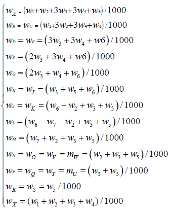
The internal section schema of left and right line parallelism and equal height as shown in Figure 2. Set the point i i( xi, yi, zi ) of the center line of right line in fully parallelism and equal height section, the transverse distance of the internal section points to point i is calculated as follows:
 (1)
(1)
Where points A to R are on the left side of the center line of the right line and points S to X are on the right side of the center line of the right line.
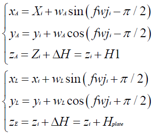
Taking the A and X points as an example. Coordinates of the two points are calculated as follows:
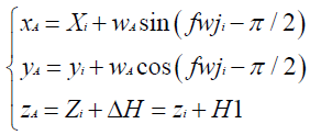 (2)
(2)
 (3)
(3)
In the formula, Fwji is Azimuth of the forward direction of the line in point i.
Calculation of right line internal cross section coordinates of incomplete parallelism and equal height section
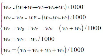
The right line in incomplete parallelism and equal height section, its internal section diagram is shown in Figure 4. Set the point i (xi, yi, zi ) of the center line of right line in incomplete parallelism and equal height section, the transverse distance of the internal section points to point i is calculated as follows:
 (4)
(4)

Figure 4. Internal section diagram of right line in incomplete parallelism and equal height section.
Where points M to R on the left side of the center line of the right line and points S to X are on the right side of the center line of the right line.
Take the points M and X as an example to calculate the x, y coordinates:
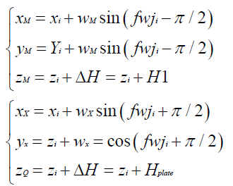 (5,6)
(5,6)
Calculation of left line internal cross section coordinates of incomplete parallelism and equal height section
The left line in incomplete parallelism and equal height section, its internal section diagram is shown in Figure 5. Set the point i ( x, y, z ) of the center line of right line in incomplete parallelism and equal height section, Where points A to F are on the left side of the center line of the left line and points G to L are on the right side of the center line of the left line.

Figure 5. Internal section diagram of left line in incomplete parallelism and equal height section.
Taking the A and L points as an example, the coordinates of the two points are calculated as follows:
 (7,8)
(7,8)
3D Coordinate Calculation of Tunnel External Section
In the design of urban rail transit tunnel, in the design of urban rail transit tunnel, the basic shapes such as arc arch, trapezoid arch, and elliptical arc arch are usually used. In this paper, taking the elliptical arc arch and circular typical tunnel section as an example to study the 3D coordinate calculation of tunnel external section.
Coordinate calculation of tunnel section in left and right line parallel segment
In the parallelism and equal height section of left and right line, the tunnel section adopts arc arch form, as shown in Figure 6; the tunnel bottom schematic diagram is shown in Figure 7. If the small deflection of the section itself is not considered, Set the half width of double line section.

Figure 6. Internal section diagram of left line in incomplete parallelism and equal height section.

Figure 7. The tunnel bottom schematic diagram.
Is WD, the half width of single line section is WS , Ellipse long axle length is a, short axle length is b, there are:
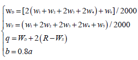 (9)
(9)
In the formula, R is the radius of the single line section (m).
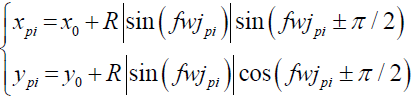
Set ellipse section center C0 ( x0, y0, z0), elliptical section angle is δ= 5/2π, when i €[0,36], the coordinate of point i is Pi (xpi, ypi, zpi) , the azimuth of its cross-section is fwjpi = −π / 2 + iδ coordinates are :
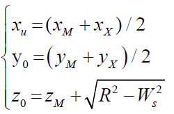 (10)
(10)
The point Pi coordinates on the ellipse are:
In the formula, when fwjpi ∈[0,π / 2] take “+” sign, when fwjpi ∈[−π / 2,0] take “–“ sign
Coordinate calculation of tunnel section in incompleteparalleling segment
The cross-section of the left and right incomplete- paralleling tunnel sections takes circular form, as shown in Figure 8; the bottom scheme of tunnel in Non-parallel section is shown in Figure 9.

Figure 8. The sectional schemes of tunnel in non-parallel single line.

Figure 9. The bottom scheme of tunnel in non-parallel section.
If the small deflection of the section itself is not considered, Set the half width of single line section is:
Wsingle, the radius of circle is R, there are:
WSingle= ( w1+w2+w3+w4 ) / 100 (11,12)
Set circle center of section is C0(x0, y0, z0), circle section angle is δ = 5 / 2π when i∈[0,72], the centre coordinates are calculated as:
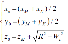 (13)
(13)
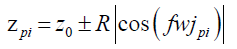
The coordinates of point Pi on the circumference are:
 (14)
(14)
In the formula, when fwjpi ∈[0,π / 2], takes “+” sign; when
fwjpi ∈[−π / 2,0] takes “-” sign
 (15)
(15)
In the formula, when 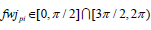 takes “+” sign; when
 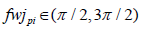 takes “-” sign.
Coordinate calculation of tunnel section in transition section
When single line tunnel is separated or merged, the intersection tunnel modeling problem is more complex than the general tunnel model. The paper adopts the gradual processing method of transition section to solve the problem, The implementation as follows: In the transition section, The tunnel still is double - lane tunnel, The tunnel line is gradually changing between the two- lane parallel and left and right single-line running, The schematic diagram is shown in Figure 10.

Figure 10. Tunnel transition section schematic diagram.
(1) The corresponding point pair (Pz, Py) which in the left and right lines on the transition section, and take them tangent angle and the length relative to the full parallel endpoint as the standard, The standards are as follows:
• When the tangent angle is greater than the limit value or the relative length is greater than the limit length, the tunnel is in a single run state.
• When the tangential included angle is less than or the relative length is less than or the relative length is less than or equal to the limit length, the tunnel is in double parallel state.
• When the tangent angle is equal to the tangent or relative length is equal to the limit length, which is the end point of double-line tunnel, and the starting point of single-line tunnel.
(2) The geometrical position determination of Pz and Py Due to the deflection of tunnel section and change of cross-section size, more tunnel sections need to be added in the direction of the road to ensure that the change of the tunnel model is not too abrupt. Set by Mileage is MB, its coordinates By (xby, yby). At the By position, do the tangent normal and Intersect with left line in Pz. At the Pz position, do the tangent normal and intersect with right line in Pz.
(3) Plane coordinate calculation of Pz and Py.
• Pz coordinate calculation:
Along the normal of By point tangent and moved two straight line spacing to the left line to obtain point Cz, It’s easy to know that point Pz in the ByCz line segment. It is also known that Pz is located in a straight line segment of a left line or a small line segment of a composition curve, set the straight line segment is DE, as shown in Figure 11.

Figure 11. Tunnel transition section schematic diagram.
By(xby , yby), Cz(xcz , ycz), D(xD , yD) and E(xE , yE)are easy to get, Then the Pz coordinates (xpz , ypz) can be obtained by the two-point simultaneous binary linear equations
• Py coordinate calculation:
The Py coordinate calculation method is the same as Pz, whose mileage is MA, the mileage of Py is:
According to the mutual calculation of mileage and coordinates, the coordinates of the Py can be calculated (xpy, ypy).
First, Mpy increases the step size ΔM and checks whether the tangent angles of Pz and Py meet the requirements:
1) If meet the requirements, and then check if the Py mileage is exceeded. If not exceeded, then recorded Pz and Py and increase Mpy step size ΔM, Calculate the new Pz and Py; If exceeded, then decreased Mpy value of Mpy so that the angle taken to the limit angle value, and recorded Pz and Py value. The APy M corresponding to the limit angle value shall be determined according to the following method:
① n=1.
② Subtract from the current Mpy.
Calculate the corresponding Pz and Py, determine whether the tangent angle is equal to the threshold value. If not equal to then turn ③, else turn ④.
③ Set n=n+1 If exceeded, turn ②; If not exceeded, Mpy increased by , calculate the corresponding Pz and Py, and determine whether the tangent angle beyond the limit.
④=A Py Py MM, recorded Pz and Py which corresponding to the limit angle value and stopped the iteration.
2) If the angle does not meet the requirements, then follow the above determination algorithm of MApyto make the angle equal to the limit angle value, and record Pz and Py.
(4) Determine the location of tunnel section.
The connection between Pz and Py is used as the cross section of the tunnel, Pz and Py are used as the left and right line points to calculate the remaining double-line coordinates, And the cross-section coordinates of each single-line are calculated at the end of transition section.
Realization of Tunnel 3D Modeling
Data structure design of tunnel modeling
In order to meet the characteristics of urban rail transit tunnels, the tunnel external cross-section model consists of multiple arcs, that is, a series of adjacent sections of the node and formed the arc. Through the two adjacent sections of the tunnel cross-section data connection, the multi-faceted data model is used to compose the patches. The schematic diagram is shown in Figure 12.

Figure 12. Schematic diagram of tunnel patch.
The tunnel data structure is defined as follows: public struct t3D Point // 3D point data structure:
{
public double Longitude; // latitude
public double Latitude; // longitude
public double H; // height
}
// Tunnel Patch data structure
public struct Tunnel Coordinates
{
// 4 vertex coordinates of tunnel Patch
public t3DPoint P1;
public t3DPoint P2;
public t3DPoint P3;
public t3DPoint P4;
}
public static List<TunnelCoordinates> m_Tunnel Coordinates ;// Stores tunnel data
The tunnel model is formed by the patch connection as shown in Figure 13.

Figure 13. Schematic diagram of the tunnel model.
Tunnel 3D model generation
On the basis of calculating the three-dimensional coordinates of the tunnel, the surface model is adopted to realize the 3D modeling of the tunnel, as shown in Figures 14a-14d.

Figure 14a. Single-hole single-line (non-parallel).

Figure 14b. Single-hole double-line (parallel).

Figure 14c. Single-hole double-line (parallel).

Figure 14d. The left and right lines separation transition segment.
Fusion of tunnel and 3D scene
In order to observe the underground line from the ground to the overall direction used transparent fusion technology and the depth of the buffer technology to achieve the terrain scene and the underground tunnel visible at the same time results. The transparent tunnel 3D model rendering is shown in Figure 15.

Figure 15. Spatial direction of underground tunnel.
According to the characteristics of urban rail transit lines, the paper adds multiple feature points control methods for cross-sections of lines, the internal section diagram of tunnel suitable for both single-line and double line is established, the coordinate calculation of three-dimensional section of tunnel is realized. On this basis, the multi-face data model is used to establish the tunnel section, and the three-dimensional modeling of the tunnel is realized. The paper adopts transparent fusion technology and deep buffer technology to realize the fusion of terrain scene and 3D scene of underground tunnel. The paper establishes a comple te three dimensional modeling method for urban rail transit tunnels, the example shows that the modeling method has good practicability and versatility it can well meet the needs of threedimensional modeling and landscape simulation of urban rail transit tunnel. The paper realizes the three-dimensional modeling of standard tunnel section, in the next step, the modeling method of horseshoe shaped tunnel needs to be further studied.
This research was supported by the National Natural Science Foundation of China (Project No.: 51278316); National Natural Science Foundation of Hebei Province, China (Project No.: E2016210133); The Project of Introducing overseas student funded of Hebei Province, China (Project No.: CL201720).
Journal of Civil and Environmental Engineering received 1798 citations as per Google Scholar report


