Research Article - (2019) Volume 9, Issue 2
Received: 29-Oct-2018
Published:
19-Mar-2019
Citation: Gebremedhn Z, Qiao G, Li J (2019) The Influence of Differential Settlement
Analysis for the Single and Multi-Combined Longitudinal Precast Box Culvert.
J Civil Environ Eng 9: 334.
Copyright: © 2019 Gebremedhn Z, et al. This is an open-access article distributed
under the terms of the Creative Commons Attribution License, which permits
unrestricted use, distribution, and reproduction in any medium, provided the original
author and source are credited.
This paper presents the influence of differential settlement analysis for the single and multi-combined longitudinal precast box culvert subject to loading conditions and deferential settlement. These precast box culvert was investigated with limit deformation for single and multi-box culvert which is connected using screw bolt formed a rigid and flexible connection in a certain non-uniform settlement interval. Farther over, the finite element method was used to analyze the numerical solution of the problems under the condition of assembled of the standard three dimensional double box culvert with soil mass and floor reaction under different loading conditions located on right side soil of box culvert which is using brick element in ABAQUS software. The culvert was modeled as per Chinese Code of standard parameters using three dimensional solid elements having geometric and material non-linearity. Finally, the deformation foundation resistance of the box culvert is the space between the multi-box culvert joint and the single box culvert length. Besides the screw bolt connection have a negative impact on the performance of the side wall of combined longitudinal box culvert.
Precast box culvert; Collision; Deformation; Finite element modeling; Finite element analysis; Screw bolt analysis
Box culvert is a reinforced precast concrete which consists of two symmetrical box culvert jointed by screw bolt formed longitudinal combined box culvert. It is preferable due to simple construction, reduces construction time and maintenance cost. In addition to this, it has good adaptability to uneven settlement of foundations and is widely used in water conservancy, railway, highway and bridge engineering but not recommended for areas with excessive settlement where deep foundations are required since deep foundations would have to be placed on shorter intervals with the use of precast sections making the installation excessively expensive. Its concrete structural must be strong, safe, stiff, reliability and economical. Its structural simplification is generally simplified and verified for single and multi-box culverts [1- 7] (Figure 1). At the present, the precast box culvert mainly used two methods for simplifying the deformation and the screw pressure. One is the upper and bottom of occasion extreme resistance limit settlement of single and multi-box culvert within a certain interval. In addition to this, the collision of two combined box culverts had rotated and formed vertical displacement difference between each other which is drawn by Autocad software (Figure 2). If the box culvert connected by four bolts but the soil under the bottom of a box culvert is lost due to a disaster (Figure 3) the strength of the bolts connecting the two box culverts should be checked by considering the bolt stress, selection of bolt type, pull shear action and screw pressure [8]. The other is the finite element method was prepared for the single and multi-box culvert, floor reaction and soil including both side soil under loading condition and differential settlement. The models included three dimensional solid elements being geometric and material none linearity. Thus, the contact between them was modeled using surface-to-surface contact elements. The load was applied on the right side of the longitudinal box culvert soil and on the hole for stress of the concrete hole around the bolt. However, the direct result obtained by the finite element method is deformation and stress of the concrete hole around the bolt. Finally, the longitudinal limit deformation of single box and multi-box culvert with rigid and flexible connection in a certain differential settlement. Furthermore, the finite element model is used to simulate the numerical solution of the problems under the condition of assembled box culvert using ABAQUS software and the results of the simplified analysis are verified [9-13] (Figure 1).

Figure 1. Sketch for calculation of reserved space for box culvert.

Figure 2. Soil loss of spliced box culvert.

Figure 3. Typical combined double box culvert and its corner numbering.
Deformation of longitudinal box culvert
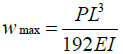
When the foundation of the box culvert is buried along the longitudinal direction of the box culvert. The limit clearance of temporary longitudinal connection is 9 mm. The formula for calculating limit settlement will be as shown in Eq. (1).
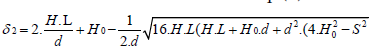 (1)
(1)
Where δ2=the box of the upper and bottom of occasion extreme resistance settlement (mm), H=distance from top of box to water proof material, H0=Outside box, L=Length box, d=Limit clearance of connection part and S=Differential settlement interval, S≤ 4r+2.H0, According to Eq. (2) it is calculated that the δ2=24 mm, it means that when the foundation is in the 40m interval. The maximum deformation can be obtained 24 mm with a nominal size as shown in Figure 1 can be used.
Collisions of box culvert
The collision modes of two transverse box culverts are rotated
and phase with the box direction. There is a vertical displacement
difference between each other. For simplified calculation, the vertical
displacement difference for the pre assembly box culvert is considered,
taking into account the uncertainty of foundation deformation, the C
horizontal displacement is reserved. The spacing is also reduced by half.
Finally, the horizontal displacement of H points is taken up with the
82 horizontal displacement of 1/2 C points.  Is taken as the
lateral reserved space of the single box culvert, the corner number is
shown in Figure 1. The Sketch for calculation of reserved space for box
culvert is shown in Figure 2.
Is taken as the
lateral reserved space of the single box culvert, the corner number is
shown in Figure 1. The Sketch for calculation of reserved space for box
culvert is shown in Figure 2.
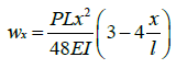
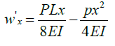
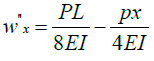
First, we should find the maximum inclination angle of box culverts using the equation below when the uneven settlement interval is 40m. It is assumed that the transverse deformation curve of the soil is within the range of 40m, which is approximately equal to the fixed ends. The deflection curve under the action of the concentrated force with l /2 distance which is supposed to indicate the instance of box culvert.
 (3)
(3)
 (4)
(4)
 (5)
(5)
 (6)
(6)
When the uneven settlement interval is 40m, maximum deformation also 24 mm, wx"=0 and x=l / 4. So that we can find the maximum inclination angle of the box culvert when tanθ1 wx` gives 0.018 and θ1=arc, tan 0.018 also when gives 1.03. This implies that the geometric condition of cross section of box culvert can be cross checked in the upper right corner when the foundation deformation is most unfavorable.
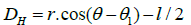
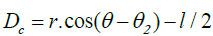
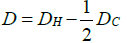
The horizontal displacement is calculated according to Eq. (7) by considering DH=58.88 mm according to Eq. (8) and DC=56.67 mm according to Eq. (9) and the spacing between two transverse culverts are 20 mm by subsisting x2=x1+l/2+20. It gives 12.38 mm.
 (10)
(10)
 (11)
(11)
 (12)
(12)
That is to say, in the two sections of the above engineering conditions, the box culvert with a nominal size as shown in Figure 1 adopts flexible connected box type. When the box culvert is assembled, the spacing between sides should not be less than the horizontal displacement which is used Eq. (14) gives 30.55 mm.
Screw bolt analysis of box culvert
The four bolts are used for rigid connection on the side of double box culvert, as shown in Figure 1. When the foundation around a box culvert subsides or the soil under the bottom of a box culvert is lost due to a disaster, the strength of the bolts connecting the two box culverts should be checked by considering the bolt stress, Selection of bolt type, pull shear action and screw pressure. The uniform load on the surface of single box culvert is shown in Table 1 [14].
| Base plate Load (q1=N/m) | Top plate Load (q2=N/m) | Side plate Load (q3=N/m) | Under side plate Load (q4=N/m) |
|---|---|---|---|
| 90.95 | 83.32 | 40.55 | 65.89 |
When the soil around a section of box culvert is lost under a certain floor due to a disaster, the earth pressure on the bottom plate of this section of box culvert disappears at this moment as shown in Figure 3. The stress of a single connection bolt can easily have obtained according to static equilibrium conditions and the simplified calculation diagram is shown in Figure 4.

Figure 4. Sketch of calculation.
The stress of a single connecting bolt can easily have obtained according to the static equilibrium condition.
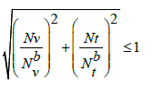
When N1=177.117 KN, N2=177.177 KN, V1 and V2 also 107.321KN. This implies that, and the bolt is pulled positively. Besides when grade C bolt selected (M45C)d=45 mm2. So that the stress of the bolt obtained Ny=107.321 KN, N t=177.117 KN and its effective area will be Ae=1306 mm2. The strength checking formula of the bolt under the pull shear action is used Eq. (15). Therefore, its tensile shear strength can be obtained 0.93 ≤1. This implies the selected bolt meet the tensile shear strength requirement.
 (13)
(13)
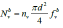
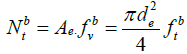
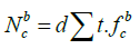
Furthermore, the design value bearing capacity of bolts also known using Eq. (17). So that its screw pressure design N v=107.321 KN ≤ Ncb=2470.5 KN. Therefore, the selected bolts meet the screw pressure design requirement.
Finite element modeling
To study the behavior of the entire possible standard double box culverts three dimensional finite element model were prepared for the standard size of box culvert as per [15]. This study dispute the [16] partially disagree with the model included 3-D solid elements soil (C3D8) and 3-D solid elements for concrete (C3D8) having geometric and material linearity. The soil was loaded on an area of 100cmX 200cm. The settlement and stress concentration area around the bolt were studied for all the load steps of double box tested using brick element [16,17].
Basic parameters of FEM
Methods comparing with each other, the finite element software ABAQUS was used to model and analyze. The displacement of two culverts including reaction floor with overlying soil on both side was calculated when the two culverts were rigidly connected and the gap between them was fixed. The corresponding settlement deformation diagram was obtained. Because the elastic modulus of box culvert and soil is four orders of magnitude different, only the elastic vertical displacement of soil is observed, and the box culvert is considered as a rigid body, and its elastic deformation can be neglected. The culvert direction is 2m per section. The finite model parameters of Material properties of soil, concrete and reaction floor were defined using standard properties. Size, Unit type, Modulus of elasticity, Poisson’s ratio and Density standard value were incorporated the basic material parameters of the modeling as per [15] shown in Table 2 and Figure 5.
| Item No. | Size (m) | Unit type | Modulus of elasticity (MPa) | Poisson’s Ratio | Density (Kg/m3) |
|---|---|---|---|---|---|
| Soil | 50 × 50 × 50 | C3D8 | 4.00E+07 | 0.3 | 2000 |
| Box culvert | 2 × 2 | C3D8 | 3.25E+10 | 0.3 | 2400 |
| Floor Reaction | 50 × 5.22 | C3D8 | 3.25E+10 | 0.3 | 2400 |

Figure 5. Binding contact (Tie) between beneath soil, both side soil and floor reaction.
The typical parts used in the FEM of this study are presented in Figure 6 which consist of precast double box culvert overlaying soil on both side with total length of 20 m including 10 section as well as the reaction floor was laid and form as contact pair. During modeling of this longitudinal precast box culvert created three surface. Those are between two internal side faces of box culvert, both side soil and beneath soil including floor reaction, and external side soil, floor reaction and external side of both box culvert. Which is left side of box culvert, beneath soil, external side of both box culver, made as master surface but right side box culvert, both side soil including floor reaction, external side soil, floor reaction was assigned to be the slave surface (Figures 5-7).

Figure 6. Binding contact (Tie) between both box culverts.

Figure 7. Binding contact (Tie) between side soil, reaction floor and box culvert.
Connection form and boundary condition
The adjacent double box culverts to the connection form and the boundary condition are connected by screw bolts. The screw bolt constraint is equivalent to the binding contact sections of the two culverts, that is, the binding contact (tie) between left and right inner face of the box culvert using surface to surface contact elements considered as the left box culvert as master surface but the right box culvert as slave surface as shown in Figure 5.
The friction contact between the box culvert and the soil of the lower box is the same as the binding contact (tie) between the box culvert and the soil. It is considered that the box culvert will contact surface to surface element on the soil surface during the analysis. There is a compression relationship between the box culvert and the soil on both sides. Therefore, when the box culvert is subjected to settlement and torsion around the long box, the soil will provide a favorable hindrance, i.e., close contact with the side of the box culvert, so the side of the box culvert is bound to the side soil by considering separately master surface and slave surface as shown in Figures 6 and 7.
Load application
In order to correspond to the step by step loading of the test process, loads are located on the right side culvert soil on a 1m x 2m area, as shown in Figure 8. The settlement displacement of the lower right corner of the right culvert is controlled to be 20 cm and loaded according to Table 3. The settlement displacement of the lower right corner is approximately satisfied by ABAQUS software calculation. The load of various parts of soil is shown in Table 3 [18].

Figure 8. Typical diagram of load location.
| Event | No soil on both side | Free soil on both side | Soil on both side | Free soil on both side |
|---|---|---|---|---|
| Load (N/m) | 7E7 | 6.2E7 | 1E8 | 1E8 |
Finite element modeling of concrete hole around bolt
In order to check the coagulation strength of the stress concentration area around the bolt, the box method is used to apply the force on the bolt to the bolt hole, that is, N and acting on the reserved bolt hole in the box culvert are used to get the stress diagram near the concrete hole wall. The effect of reinforcement bar near the bolt hole is not considered in the modeling. Because the effect of the compression distribution of reinforcement in the culvert is insignificant. Thus, the finite element model parameters are shown in Figure 6 based on 212 (Table 2) [15].
Finite element analysis
The output database files in ABAQUS were read by visualization module to create contour plots, animations, XY plots, and tabular output of the results. Crack is not supported by visualization mode so it is read in data file, which identifies the cracked elements and the level of stress at that point [19-21].
According to the results of software calculation, the deformed and un-deformed form of the combined box culvert is obtained, as shown in Figures 9 and 10. The corners are numbered respectively, as shown in Figure 1. The horizontal and vertical displacement of each corner point is calculated by the ABAQUS software. The horizontal displacement is positive to the right, and the vertical displacement is positive downward, as shown in Table 4.

Figure 9. Typical deformed and un-deformed Shape of the flexible joint double box culvert.

Figure 10. Typical deformed and un-deformed shape of the rigid joint double Box culvert.
| No | Joined without side soil displacement (m) | Free soil joined on both side soil displacement (m) | Joined soil on both side soil displacement (m) | Free soil without joined both side soil displacement (m) | ||||
|---|---|---|---|---|---|---|---|---|
| Vertical | Horizontal | Vertical | Horizontal | Vertical | Horizontal | Vertical | Horizontal | |
| A | 0.17 | 0.002 | 0.151 | 0.015 | 0.298 | 0.02 | 0.299 | 0.015 |
| B | 0.139 | 0.002 | 0.123 | 0.015 | 0.206 | 0.02 | 0.204 | 0.015 |
| C | 0.148 | 0.002 | 0.131 | 0.015 | 0.249 | 0.02 | 0.249 | 0.08 |
| D | 0.178 | 0.002 | 0.158 | 0.015 | 0.329 | 0.19 | 0.332 | 0.08 |
| E | 0.139 | 0.002 | 0.123 | 0.015 | 0.206 | 0.19 | 0.204 | 0.015 |
| F | 0.11 | 0.002 | 0.098 | 0.015 | 0.119 | 0.19 | 0.12 | 0.015 |
| G | 0.121 | 0.002 | 0.107 | 0.015 | 0.18 | 0.042 | 0.18 | 0.048 |
| H | 0.148 | 0.002 | 0.131 | 0.015 | 0.249 | 0.043 | 0.244 | 0.049 |
According to the Table 4, the maximum horizontal displacement difference between H and C is 31 mm, which is approximately
equal to 30.5 mm. In simplified calculation, because there are many assumptions and also it is more partial safety. Compared with two working conditions of side soil, it is found that the settlement of left double box culverts is less than that of right double box culverts. This is because the deformation of the right lower box soil has little effect on the left side of the culvert when the two culverts are free, and when the two culverts are just joined, the deformation of the left and right culverts is coordinated, resulting in the left side of the culvert will be driven to settle together. From the Figure 11, it can be seen that when the two culverts are free, the right side culvert turns around the long box to a certain extent. Comparing the horizontal box displacement of CD two points in the Table 4 can also reflect this problem. Because only 10 box culverts are connected in series. In this case, the torsional stiffness of the longitudinal box direction is smaller than that of the actual production because of horizontal displacement is larger (Figure 12).

Figure 11. Vertical displacement (settlement) of double box culvert for each corner point.
Finite element analysis of concrete hole around bolt
In order to check the coagulation strength of the stress concentration area around the bolt, the box method is used to apply the force on the bolt to the bolt hole, that is, N and acting on the reserved bolt hole in the box culvert are used to get the stress diagram near the concrete hole wall. The effect of reinforcement bar near the bolt hole is not considered in the modeling. Because the effect of the compression distribution of reinforcement in the culvert is insignificant. Thus, the finite element model parameters are shown in Figure 6 based on Table 2 [15].
This paper has presented an influence of differential settlement of the single and multi-combined longitudinal precast box culvert subject to loading condition and deferential settlement. The main simplified variables included the deformation (vertical displacement and horizontal displacement) and stress of concrete hole side wall. Based on interpretations and discussions of the simplified results, the following conclusion can be emerged;
1. The main factors of the resistance foundation deformation of the box culvert are the clearance of the longitudinal box culvert joint and the length of the single box culvert. If the longitudinal box culvert joint can be changed to make it have better deformation ability the box culvert to resist foundation deformation can be improved significantly.
2. The staggered bolt connection will destroy the compactness of the side wall of the box culvert, lead to the invasion of water vapor in the soil, and have a negative impact on the performance of the internal utility line and precast concrete itself. When the soil is not uniform settlement, the moment between the box culvert due to gravity and earth pressure acts on the staggered 271 bolt, which will produce local compression on the concrete of the side wall of the bolt hole, leading to concrete cracks and damage in advance. If the space between the two transverse box culvert sections is satisfied using M45 grade C bolt connection, the two single box culvert can work independently without collision under a certain limit of ground deformation.
This research was financially supported by the National Key Basic Research Program of China (973 Program CSC No.2016GXZ133) and Zhonda Road and Bridge Group.
Journal of Civil and Environmental Engineering received 1798 citations as per Google Scholar report


