Research Article - (2021) Volume 11, Issue 12
Received: 29-Jul-2021
Published:
22-Dec-2021
Citation: Melese, Wubetu Fekadu and Henok Fikre Gebregziabher. “Behavior of Structurally Non-connected Settlement Reducing Piles under Raft Foundation” J Civil Environ Eng 11 (2021): 428.
Copyright: © 2021 Melese FW, et al. This is an open-access article distributed under the terms of the Creative Commons Attribution License, which permits unrestricted use, distribution, and reproduction in any medium, provided the original author and source are credited.
Piles act as a settlement reducer in case of connected piled-raft foundation and hence decrease the settlements of the raft. The design concept of the connected piled-raft foundations is to lessen the number of piles and utilize the bearing capacity entirely. Due to significant straining actions at the pile head-raft connection, an alternative technique is proposed to disconnect the piles from the raft. A Granular layer (cushion) beneath the raft is incorporated. The disconnection has a beneficial effect on reducing axial load compared to connected piles. For small piled rafts, non-connected piled rafts show less stiffness than connected piled rafts, and the soil is highly stressed and shows greater raft settlement. In the case of the large piled raft, non-connected piled rafts show greater settlement efficiency. However, as compared to the non-connected piled raft, the connected piled rafts show a significant reduction in raft settlement as pile spacing increases. The results show that the load transfer mechanism in a nonconnected piled raft is mainly governed by the thickness and stiffness of the cushion layer and by the stiffness of the subsoil.
Connected piled raft • Non-connected piled raft • Settlement reducer pile • Cushion • PLAXIS 3D
For given load circumstances, shallow foundations are acceptable foundations when suitable bearing stratum is present at a shallow depth. The use of deep foundations is required if the load from the structures would lead to excessive settlements. Conventionally piles are added for load bearing capacity and settlement reduction requirements. It is assumed that piles were designed to carry the entire load of the structures. In this case large number of piles was utilized. However, Burland JB, et al. [1] discussed the idea of using a few piles to reduce the settlement to a required level and to improve the state of stresses in the raft. The piles are therefore termed as ‘‘settlement reducers’’. As the name indicates, the main purposes of introducing settlement reducer piles are only to satisfy the settlement requirements. As mentioned by Poulos and Davis to reduce settlements to permissible value, usually small numbers of piles are sufficient, and further addition of piles may result in only marginal further reductions in settlements.
Conventionally, piles were designed to take all external loads and there is a margin for the pile to reach either its geotechnical bearing capacity or its structural collapse load.
Randolph MF and Clancy, [2] considered that for competent design of rafts with settlement-reducing piles, 80% of pile capacity mobilization can be assumed under working load. In this regard, a lower factor of safety can be applied to the geotechnical capacity of the piles and the bearing capacity of the raft is alone adequate. In usual cases, piles are cast monolithically with the rafts, called “connected settlement reducer piles”. Since few numbers of piles are adequate to reduce the settlement to permissible value, and however if these piles are connected to the raft, concentration of high axial stresses in the pile heads may develop and their load-carrying capacity will be governed by their structural capacities rather than by geotechnical capacity. They often lead to significant straining actions at the pile head-raft connection [3].
Wong IH, et al. [4] identified the problems associated with structurally connected settlement reducing piles and clearly discussed alternative solutions, which is adoption of non-connected settlement reducer piles, known as non-connected piled raft foundation (NC), in which the raft-pile connection is detached. In case of disconnected piled foundation system, there is no structural connection between the piles and the raft and gap is usually filled with granular material (cushion). Some studies have been devoted to the effect cushion on the disconnected piled raft performance [5-9]. Baziar MH, et al. [9] investigated that proper grading of the load transform platform can advance the axial stiffness of disconnected piled raft foundation system.
Several authors have recently presented results of numerical simulations [4-6] or 1 g model tests concerning rafts on disconnected settlement-reducing piles [7], and multi-g centrifuge tests [8,9].
Practically, recently in some projects, the piles are detached from the raft by a cushion layer, which creates a more uniform pressure distribution on the raft bottom and reduces constraint reactions in the soil, foundation, and superstructure. Among these, the foundation system of the Rion Antirion Bridge, in Greece, [10] and the recently super long-span Izmit Bay bridge consists of vertical inclusions (disconnected piles) to improve the shear resistance of the foundation soils and to minimize the hazards related to differential settlements, plus a gravel bed to limit the shear forces and moments transmitted between the superstructure and the foundation soils.
Cao XD, et al. [7] evaluated the effectiveness of non-connected piles as a settlement reducer by subjecting small scale non-connected piled raft foundation to vertical loading. These piles were used as the soil reinforcing elements instead of as the structural elements. The result indicated that non-connected piles were effective in the reducing settlement and bending moments at the piles head.
Similarly, Ghalesari T, et al. [11] studied the effect of cushion layer on both connected and disconnected piled raft foundation. The result shows that gravel layer thickness has a significant effect on the maximum and differential settlements of the foundation.
The load transfer mechanisms of disconnected piled raft greatly differ from those of a raft with piles in connected; because of the compressibility of the layer, which permits a relative raft–pile displacement, a relative downward displacement of the soil, with respect to the upper part of the pile, takes place and gives rise to negative skin friction. Cao XD, et al. [7] and Fioravante V, et al. [8] suggests that such a mechanism is influenced by the thickness and the stiffness of the cushion layer and by the stiffness of the soil. A disconnected pile serves mainly as a reinforcement of the subsoil, enhancing the stiffness of unpiled raft.
El Sawwaf M [12] experimentally study of the effectiveness of using both connected and non-connected short piles to the raft on the behavior of an eccentrically loaded raft. The test indicates that the use short piles near to the raft edges not only significantly enhance the raft bearing pressures but also leads to a reduction in raft settlements and tilts leading to an economical design of the raft.
Many studies concerning the analysis of non-connected piled raft foundations have been proposed by various researchers [4,8,12]. However, most of them do not incorporate the effect of cushion and load sharing and carrying mechanism of piles in a non-connected piled raft foundation. In this research, effect of variation cushion thickness, pile number, raft thickness, cushion and subsoil stiffness on load sharing and settlement efficiency of nonconnected piles are studied in detailed.
Load transfer mechanism
Non-connected piles are partially loaded from the raft, which is arching effect, and partially through the skin friction (negative) at the top part (Figure 1). Previous researchers Tradigo F, et al. [6], Cao XD, et al. [7], Fioravante V, et al. [8], Zhu, and Rasouli HA, et al. [11] show the development of skin friction distribution along the pile shaft. The maximum axial force (Nmax) found some depth below the pile head, as a consequence of the negative skin friction along the upper portion of the piles, whereas in connected piled raft foundation (PRF) it is found at the pile head.

Figure 1. Negative skin friction in non-connected piled raft foundation (NC).
It is evident that negative skin friction governed the load transfer on the upper part of the piles, while positive skin friction governed the load transfer on the lower part of the piles [7]. Load carrying capacity of piles and raft is complex due to interactions between the piles, the subsoil, and the raft (Figure 2). However, load sharing in a disconnected piled raft is even more complex due to a deformable cushion layer between the piles and the raft [6].

Figure 2. Interactions between soil and structural members R=raft; P=pile; S=soil.
Cao XD, et al. [7] reported that disconnected piles carry a load of 30-35% of the applied load. This is due to detachment of piles from the raft and piles did not receive the load directly. This amount of load sharing is similar to the 32% reported by Horikoshi K and Randolph MF [3] for design conditions that lead to 80% mobilization of pile capacity.
Pile–subsoil relative displacement can be more quantitatively described by introducing, a normalized ratio as follows [11]
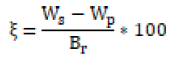
Where Ws, Wp, and Br are subsoil settlement, piles, and the raft breadth, respectively. At the top parts of the piles, subsoil settlement in the nonconnected piled raft is larger than settlement of piles. The greater values of ξ mean the larger relative pile–soil displacement and larger negative skin friction (NSF).
Finite element modelling
Finite element method is popular in recent years in geotechnical engineering. A variety of finite element computer programs have been developed with a number of useful features and to suit different requirements. The analysis method in this study refers to three-dimensional finite element methods (FEM) via PLAXIS 3D 2020 connect edition software.
Pile modelling options in PLAXIS 3D: Two pile modelling alternatives was extensively compared by previous researchers Lee et al, F. Tschuchnigg, F. Tschuchnigg et al and Tradigo et al. [6], use of either volume element (3D) or embedded pile (EP) elements (1-D element). 3D finite element analyses allow accounting geometrical irregularities and material nonlinearities. However, large number of piles leads to computationally demanding models that may be beyond the capabilities of the code or simply take too long time to analyze [6] (Figures 3-5).

Figure 3. Discretized volume raft and piles.

Figure 4. (a) Embedded pile and (b) volume pile.

Figure 5. Staged construction of FEM in PLAXIS 3D.
The benefit of embedded pile is that piles can cross finite elements in any direction and do not influence the finite element mesh and significant computational time can be saved [6].
Fully Solid (volume element) approaches seem to be more realistic, as they do not introduce any specific assumption on the structural behavior of the piles.
Piled-raft foundation system is a 3D complex problem, which needs 3D finite element method to be solved. Consequently, 3D volume elements are used to model all structural elements in this research. This pile-soil interaction at the true pile perimeter.
Mesh and boundary condition: From the edge of the raft, lateral soil domain boundaries of the model were placed at a distance of two and half times the width of raft (2.5 Br) and restrained against horizontal translation (i.e., horizontal displacement) but with vertical translation (i.e., vertical displacement) of soil being allowed.
The pressure bulb in a raft foundation was formed up to twice the width of raft, while that in pile raft was formed at two-third of the pile length. Thus, the bottom soil boundary was at a vertical distance of twice the width of raft plus two-third of the pile length and was restricted from both horizontal and vertical translations. Fine mesh has been selected globally for the entire soil domain and refined mesh was chosen in the vicinity of the structural elements.
Constitutive modeling: Cushion layer and subsoil material are modelled by using hardening soil model material in drained condition. Material properties used in this study were adopted from Franz.
In this research, finite element model in the PLAXIS 3D has been validated by comparing with the reported results of Fioravante V, [8]. Raft of 7.5 m × 7.5 m size and 9 piles of 0.5 m diameter with a length of 20 m were used in the study. The piles were spaced at five times of pile diameter(S=5Dp), and uniformly a distributed load of 1.22 MPa was applied on the foundation. The material properties of the soil, raft, and piles are given in Table 1.
| Material | Young Modulus, E(MPa) | Unit Wt. (kN/m3) | Poisson's ratio, ν |
|---|---|---|---|
| Raft | 30,000 | 24 | 0.15 |
| Pile | 30,000 | 24 | 0.15 |
Figures 6 and 7 indicated that the finite element result is rationally good agreement with those reported for non-conneted, and raft foundations. For continuing the accuracy of the results, similar modelling steps have been followed to model the different foundation systems of the present study.

Figure 6. Load settlement curve for validation of non-connected piled raft (9NC).

Figure 7. Load settlement curve for validation of un-piled raft (UR).
Parametric study
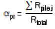
The most important results discussed in this research are load sharing ratio and settlement reduction factor or settlement efficiency ratio. The loadsharing ratio (αpr) is defined as the ratio of total load carried by the piles (Rpile) to the applied load (Rtotal) on the foundation. Rpile is the summation of axial load carried by each pile at its head.
The settlement performance of a NC and PR foundations can be quantified by means of the definition of the following settlement efficiency ratio [8].
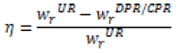
Where  are the settlements of the unpiled raft and
disconnected/connected piled raft, respectively. Adding piles improves load–
settlement behavior so that the values of
are the settlements of the unpiled raft and
disconnected/connected piled raft, respectively. Adding piles improves load–
settlement behavior so that the values of  are always smaller than
  Therefore, larger values for the settlement efficiency ratio means more efficient in reducing raft settlement.
Analysis and discussion: This section discusses the effect of cushion thickness (Hc), cushion and subsoil stiffness, pile length (Lp), pile number (Np) and raft thickness (tr) on settlement efficiency ratio (η), load sharing ratio(αpr), axial load distribution along pile length and differential settlement (ΔS/Br). Therefore, the effect these parameters on connected and non-connected foundation are presented in the following sections.
Relative raft-soil stiffness: Stiffness of raft is the main factors that control the performance of piled rafts; it influences the interactions of the raft with the piles and the soil [13-17]. The raft-soil relative stiffness (Krs) greatly influences the differential settlement of a piled raft foundation. The large raft stiffness, the small differential settlement of a piled raft, and vice versa. Therefore, raft thickness determination is very necessary. For rectangular rafts, Horikoshi K and Randolph MF [3] suggested the following equation to estimate the relative flexibility of raft.
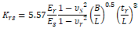
Where Er and Es = Young’s modulus of the raft and the soil, respectively; υr and υS = Poisson’s ratio of the raft and the soil, respectively; B and L = breadth and length of the raft, respectively; tr = thickness of the raft.
According to Horikosh and Randolph, [3] the raft is flexible when Krs ranges from 0.01 to 1.0. Basile F [18] recommended that rafts of Krs ranging between 5 and 10 are rigid; Furthermore, Reul and Randolph, [13] suggested the ranges of fully flexible and fully rigid Krs to be 0.008 and 54, respectively.
Effect of raft-soil relative stiffness shows a similar effect on both connected and non-connected piled raft foundation as shown in Figure 8. Figure 8a shows that the maximum settlement initially decreases with the raft thickness (stiffness) and increases very slightly after reaching a limiting raft thickness (around Krs of 1.182 for 9NC1.0 and 3.988 for 9PR in this study). i.e. tr = 1.5 and tr = 1.25 m. This is because increasing the raft thickness beyond the limit (optimum thickness) gives excessive weight to the raft and leads to additional settlement. As a comparison, the performance of non-connected piled raft is better than connected piled raft in case of the large piled raft (Br/Lp > 1).

Figure 8.Effect of raft-soil relative stiffness on (a) normalized differential settlement ΔS/ Br (%), (b) normalized maximum settlement, Smax/Br (%).
However, as the raft thickness increases the normalized differential settlement (ΔS/Br (%)) of both non-connected (NC) and connected piled raft (PR) significantly decreased (Figure 8b). But the rate of decrease in differential settlement seems to disappear at some specific Krs (around Krs of 3.988 for in this study) i.e. tr = 1.5 m.
Regarding this, recently Gebregziabher HF and Achmus M [14] reported that stiffening the raft excessively may not guarantee the effective reduction of the differential settlement, especially when the piles are closely spaced. A similar finding has been also reported by Sinha A [15]. To sum up, increasing the raft stiffness is effective in primarily reducing the differential settlement. Increasing the raft stiffness may be also useful in resisting the punching and shear [16].
The raft thickness has a very small effect on the load carried by the nonconnected piles as shown in Figure 9. Whereas for connected piles, as the raftsoil relative stiffness (Krs) increase (as raft thickness increase), load sharing ratio of piles (αpr) decreased.

Figure 9. Effect of raft-soil relative stiffness on a load sharing ratio of piles.
Piles in connected piled raft share a greater portion of the total load applied as compared to non-connected piles due to transfer of load from the raft to piles directly. However, in non-connected case insertion of cushion layer changes the load transfer mechanisms of the foundation, as the cushion redistributes the load.
Similar observations regarding the effect of raft thickness on the load sharing at small settlement levels are reported. Oh EYN, et al. [17] stated that raft thickness has slight effect on the load sharing percentage of piled-raft foundations on sandy soil. Similarly, Basile F [18] pointed out that except for thin rafts, the load sharing between the raft and the piles are little affected by the raft-soil relative stiffness (Tables 2 and 3).
| Geometry | Model dimenstion (mm) | Prototype dimension (m) |
|---|---|---|
| Raft width (B) | 115 | 7.5 |
| Pile length (Lp) | 292 | 19 |
| Pile diameter (Dp) | 8 | 0.5 |
| Pile spacing (S) | 38.5 | 2.5 |
| Thickness of cushion layer(hc) | 15.4 | 1 |
| Parameter | Material type | |
|---|---|---|
| Cushion Layer | Foundation Soil | |
| C’(kPa) | 0 | 0 |
| φ'(0) | 35 | 35 |
| γdry (kN/m3) | 16.67 | 15.3 |
| E50ref, (MPa) | 20 | 15 |
| Eoedref, (MPa) | 20 | 15 |
| Eurref, (MPa) | 60 | 45 |
| m | 0.55 | 0.5 |
| Vur | 0.2 | 0.2 |
| Ψ(0) | 5 | 5 |
| KoNC | 1-sin φ' | 1-sin φ' |
| OCR | 1 | 1 |
Effect of cushion thickness: To study the effect of variation in cushion thickness, NC was modelled with 4, 5, and 9 piles with pile length of 20 m and normalized spacing (S/D) of 5. As a comparison connected piled raft (PRF) with 4 5, and 9 piles have been modelled. For the NC case, the cushion thickness was varied from 0.5 to 3 m for parametric studies. The effects of cushion thickness on the behavior of NC foundation such as the settlement of raft, pile axial force, and subsoil settlements in comparison with unpiled raft (UR) and PR foundation were analyzed.
Figure 10 shows the variation in the subsoil settlement vs. the cushion thickness. The result shows that the maximum settlement of the subsoil decreases with the increase of the cushion thickness. As compared to raft without piles, a non-connected piled raft with 3.0 m cushion thickness has a greater settlement reduction. But as compared to a connected piled raft, NC09 with 3.0 m cushion thickness has a lesser performance.

Figure 10. Variation of normalized subsoil settlement with the cushion thickness.
In Figure 9, as the cushion thickness increases, the settlement efficiency ratio increases. However, the connected piled raft has a better performance. Cushion thickness has a significant effect on the reduction of raft maximum settlement up to 1.5 m but the further increment of the thickness has no significant effect. This result is in agreement with Baziar MH, et al. [9] reported that the optimum thickness of the granular layer in the pile raft systems in sandy soil is suggested as 1.5 m.
It shows that the axial load at the pile head decreases as the thickness of the cushion increases. As the cushion thickness increases, less force has been transferred to the piles and the settlement of the piles is reduced compared with the soil.
For any Hc value, negative and positive skin friction, whose border at z=zn marks the neutral plane associated with the maximum axial force. As Figures 4-19 show, the position of the neutral plane tends to shift downwards as the thickness of cushion (Hc) increases, while the maximum axial force (Nmax) in NC is always found to be lower than in PRs. We can see that for PR cases the maximum axial force (Nmax) generated in piles are higher than the piles in the NC case.
As the cushion thickness increases, the load sharing percentage of piles increases up to Hc/Dp of 4. However, further increasing of the thickness is insignificant. It may be deduced that the load sharing between the cushion and the piles is affected by the thickness of the cushion.
Beyond the state of art, practically many projects have been constructed with a cushion layer of 3 m depending on the site conditions. For example, the innovative foundation system of the Rion Antirion bridge consists of three 90 m and one 80 m diameter piers and includes the use of up to 30 m long, 2 m diameter non-connected steel piles to reinforce the weak foundation soils, designed with 3 m cushion layer [10]. Similarly, ICEDA (Mattsson N. et al), which is a French project constructed with 2.75 m cushion thickness under mat foundation for nuclear waste storage plants.
ASIRI, (2012) recommends a cushion thickness of 0.4-0.8 m to design a raft, particularly intending to reduce bending moments. However, the thickness suggested by ASIRI may be site-specific and particularly for raft bending moments. It didn’t address settlement efficiency and load sharing ratio of piles and overall foundation performance. Similarly, Baziar, MH et al. [9] and Rasouli HA, et al. [11] reported that by increasing cushion thickness more than a certain value (about 1.5 m), the decreasing rate of raft settlement becomes quite small and a further increase in cushion thickness will not be significant.
Therefore, Hor B, et al. [5] concluded that the designer shall evaluate the economic and technical considerations between thickening the cushion layer and strengthening the raft.
Cushion and subsoil stiffness variation: The founding soil characteristics such as cushion and subsoil stiffness slightly affect the load-bearing behavior of piled rafts [11]. Practice shows that the cushion layer inserted between the raft and piles can adjust the load-sharing ratios of piles and subsoil, and enhance the strength of subsoil among piles [9].
To investigate the effect of cushion stiffness on the performance of the unconnected piled raft system a wide range of values of stiffness was used. Length of piles was varied from 7 to 20 m, composing both small and large piled raft foundations (Table 4).
| Raft Dimension (m) | Raft Thickness (m) | Number of Piles | Cushion Stiffness (E50ref) kN/m2 | Subsoil Stiffness (E50ref) kN/m2 | Pile Length (m) | Output (Response) |
|---|---|---|---|---|---|---|
| 12 × 12 | 1.5 | 9 | 24,000 | 13,000 | 7 | Load-settlement (Settlement efficiency ratio) |
| 40,000 | 18,000 | 14 | Axial force distribution | |||
| 60,000 | 24,000 | 20 | Load sharing Ratio | |||
| 82,000 |
• Figure 14c shows that increasing subsoil and cushion or load transfer platform (LTP) stiffness increases the settlement efficiency ratio (η). For subsoil stiffness (E50ref) of 13 MPa, increasing the cushion stiffness (E50ref) from 24 Mpa to 82 Mpa, increases η value from 0.28 to 0.365. Similarly, for a cushion stiffness of 60 MPa, increasing subsoil stiffness from 13 MPa to 24 MPa increases the η by 77.4%. Increasing subsoil stiffness from 13 MPa to 24 MPa increases η by 80% with high cushion stiffness (E50ref = 82 MPa), the raft settlement of connected piled raft has no significant difference with that of the non-connected piled raft. For instance, for subsoil stiffness of 24 MPa, and 20 m pile length, settlement efficiency (η) for the connected and non-connected piled raft is 0.648 and 0.635 respectively.
• For a pile length of 14 m, a similar effect is pronounced (Figures 4-19). Rasso and Viggiani (1998) grouped piled raft foundations into two broad categories of small (raft breadth to the pile length ratio, Br/Lp <1) and large piled rafts (B/Lp >1). For large piled rafts, increasing the stiffness of cushion decreases the settlement of non-connected piled rafts(NC) even more than that of connected piled rafts(PR). Figure 14 indicates that the settlements of non-connected piled rafts with Br/Lp= 1.7 are lesser than the conforming cases for a connected piled raft. A similar result has been reported by Baziar MH, et al. [9].

Figure 11. Comparison of settlement efficiency ratio for different cushion thickness of 9NC1.0 and 9PR.

Figure 12. Variation of normalized axial force along the length of the corner pile with varying cushion.

Figure 13. Variation of load sharing ratio of piles on cushion thickness.

Figure 14.Effect of subsoil and cushion stiffness on settlement efficiency ratio (η) for 9NC1.0 (a) Lp=7 m, (b) Lp=14 m, (c) Lp=20 m.

Figure 15. Effect of cushion stiffness on typical corner pile axial force for subsoil E50ref=18 MPa (a) Lp=7 m), (b) Lp=14 m, (c) Lp=20 m and (d) Effect of subsoil and cushion stiffness on a load sharing ratio of piles (9NC1.0, and Lp=20).

Figure 16. Comparison of a normalized maximum settlement of raft for NC and PR with several piles (Lp=20 m, S/Dp=5).

Figure 17. Effect of pile number on settlement efficiency ratio for NC09/PR09, Lp=20 m and S/Dp=5.

Figure 18. Effect of number of piles on axial force distribution of corner piles for both connected and non-connected piled raft (Lp=20 m, S/Dp=5).

Figure 19. Effect of pile number on a load sharing ratio of pile.
In the disconnected piled raft foundation, existence of a cushion between piles and raft allows the relative deformation between piles head and soil beneath the raft. Put differently, if the stiffness of the cushion is not sufficient, the bearing capacity of piles will not be completely mobilized and the loading capacity of the non-connected pile raft foundation can be less than that of a connected one.
Effect of pile number: To analysed the influence pile number, simulation was performed with 4, 9, 16, and 25 piles having a length of 20 m and S/Dp of 5. Figure 16 shows raft maximum settlement vs. the number of piles for connected and non-connected piled raft system. The raft maximum settlement was reduced as the number of piles increased. As predicted, assessment of the following cases of Figure 16 shows a decrease in the rate of the raft settlement, which causes a minor difference in the settlement. Increasing pile numbers from 4 to 9, 9 to 16, and 16 to 25 are 14%, 15%, and 12% results settlement reduction in the disconnected case. Similarly, for connected piled rafts 22%, 32%, and 25% respectively (Table 5).
| Load Sharing Ratio of Piles (%) | ||
|---|---|---|
| Np | Non-connected | Connected |
| 4 | 8.75 | 20.87 |
| 5 | 11.16 | 25.55 |
| 9 | 17.87 | 41.24 |
| 16 | 26.81 | 64.05 |
| 25 | 35.54 | 73.58 |
Numerical modeling was used to evaluate the effectiveness of nonconnected settlement reducer piles under the raft foundation (NC) in terms of settlement efficiency ratio, load sharing ratio of piles and axial load distribution along the pile length. This research also compares performance of connected settlement reducer piles (PRF) with non-connected piles. The results of the parameter study show that installation of non-connected settlement reducer piles with load transfer platform (cushion layer) under raft. As compared to raft without piles (unpiled raft), non-connected piled raft shows greater settlement efficiency. It reduces the settlement up to 40% for 16 numbers of piles. Besides the result shows that non-connected piles carry about 30% of the load. The following conclusions can be drawn for conducted parametric studies.
• Non-connected foundation system mechanism is likely to be governed by the interposed layer stiffness and thickness.
• In the PR, the maximum load occurred at the top of the pile, and the axial load decreased with depth. It is also confirmed that the effect of negative skin friction of the NC, which changes the pile axial load distribution form.
• By increasing the cushion stiffness, the ratio of the sum of pile loads to the total load increases. Also, parametric studies show that the lower the cushion stiffness, the deeper the location of the neutral plane.
• For small piled raft (Br/Lp <1), non-connected piled rafts show less stiffness than connected piled rafts, and the soil is highly stressed and show greater raft settlement. Whereas in case of large piled raft (Br/ Lp >1), non-connected piled rafts show greater settlement efficiency.
• As the stiffness of the cushion layer increases from 24 MPa to 82 MPa, the load-carrying capacity of the pile decreases 49%. Cushion stiffness was realized to be more substantial for a non-connected piled raft with shorter piles than one with longer piles.
• Effect of raft-soil relative stiffness shows a similar effect on both connected and non-connected piled raft foundation It shows that the maximum settlement initially decreases with increase in raft-soil relative stiffness and increases very slightly after reaching a limiting raft thickness (around Krs of 1.182 for 9 NC1.0 and 3.988 for 9 PR for in this study). i.e., tr = 1.5 and tr = 1.25 m.
• However, as the raft thickness increases the normalized differential settlement (ΔS/Br (%)) of both non-connected (NC) and connected piled raft (PR) significantly decreased. But the rate of decrease in differential settlement seems to disappear at some specific Krs, around Krs of 3.988 (tr = 1.5 m) for in this study). It can be concluded that increasing the raft thickness (stiffness) is effective, primarily, in reducing the differential settlement.
• The raft-soil relative stiffness (raft thickness) has a small effect on the load carried by the non-connected piles. Whereas for connected piles, as the raft-soil relative stiffness (Krs) increase (as raft thickness increase), load sharing ratio of piles (αpr) decreased..
Great thanks deserve to Dr.-Ing Henok Fikre for his guidance and for Bahir Dar Institute of Technology for sponsoring master’s program.
Journal of Civil and Environmental Engineering received 1798 citations as per Google Scholar report


