Research Article - (2026) Volume 13, Issue 1
Received: 16-Oct-2024, Manuscript No. JLOP-24-150240;
Editor assigned: 21-Oct-2024, Pre QC No. JLOP-24-150240 (PQ);
Reviewed: 05-Nov-2024, QC No. JLOP-24-150240;
Revised: 10-Feb-2026, Manuscript No. JLOP-24-150240 (R);
Published:
17-Feb-2026
, DOI: 10.37421/2469-410X.2025.13.190
Citation: Muduli, Nilambar, and JSN Achary. "Analysis of Elliptical PCF Involving D Shaped Air Hole in Core for Terahertz Criterion for Optical Communication." J Laser Opt Photonics 13 (2026): 190.
Copyright: 2025 Muduli N, et al. This is an open-access article distributed under the terms of the creative commons attribution license which permits unrestricted use, distribution and reproduction in any medium, provided the original author and source are credited.
A novel PCF design with D shaped air holes in core region having elliptical air hole in cladding is proposed for optical communication. A full vector finite element method is applied to analyze the guiding properties of PCF structure for high accuracy result. The simulation result reports that the proposed PCF has a flat dispersion of 0.9 ± 0.22 ps/THz/cm at 0.8-1.2 THz, a birefringence of -0.0625 and the effective material loss of 0.061 cm-1. We theoretically investigate the important properties of proposed PCF such as confinement loss, bending loss and effective mode field area. The above PCF design is used for maintaining polarization, sensing application and also for propagation of terahertz wave.
Novel PCF • Birefringence • Bending loss • Material loss
The terahertz regime lies between microwave and infrared ranges, taking up a substantial portion of the electromagnetic spectrum. Due to its unique features, terahertz radiation has received significant attention from researchers. The Terahertz (THz) frequency band of the electromagnetic spectrum lies between the microwave and infrared regions between frequencies of 0.1 and 10 THz, or equivalently, between 30 μm and 3 mm wavelength. Terahertz waves have vast spectroscopic applications. For example, packaging materials like styrofoam, polyethene and packing tapes are transparent in the terahertz regime, making THz radiation an excellent candidate for detecting chemical and explosive substances concealed in clothing or packaging materials at busy areas such as train stations and airports. Over the years, terahertz radiation has found applications in medicine [1] and non-destructive testing in industrial quality control [2]. For example, THz radiation is used to measure the coating thickness of the F-35 fighter jet as its speciality coatings on the outside present a unique measurement challenge. Other applications of THz radiation include defence and security, art conservation and ultra-fast wireless transmission [3], astrophysics [4] and material science [5]. The photonic crystal fiber plays a significant role in the field of communication. Terahertz band in the electromagnetic and optical regime is enticing increased attention. Terahertz (THz) bands have gathered excessive interest owing to their several distinctive applications, such as optical spectroscopy [6], non–invasive medical imaging [7], characteristics of dielectric material [8], bio-sensing [9], military [10], and telecommunications [11]. Attributable to the wide advantages of PCF such as large effective area [12], high birefringence [13], flat dispersion [14], high nonlinearity [15], a single mode of operation it is preferable for efficient transmission of broadband terahertz signals. Numerous types of PCF design including metallic wires, single-mode spiral shape photonic crystal fiber, polymer fibers, Bragg fibers, hollow-core fibers, quasi pattern based photonic crystal fiber and D-Shaped Photonic-crystal Fiber have been recommended as solutions for low losses, high birefringence, low dispersion etc.
PCF has attracted extensive attention from researchers because of its design flexibility. A PCF with square lattice subwavelength air holes was proposed by Ren, et al. [16], and new progress was made in the next year to make the EML as low as 0.002 cm−1 [17], but this structure can only be obtained low birefringence of 10−3. Islam, et al. [18] proposed a hexagonal lattice diamond core PCF with birefringence of the order of 10−2 and low EML, but it has these characteristics only at 0.7 THz and has very high confinement loss, more than 0.1 dB/cm. M. R. Hasan et al. [19] proposed a spiral asymmetric PCF that provided a high birefringence of 0.0483 and an EML of 0.085 cm−1, but this structure is very complex and difficult to be applied in practice. Habib MA, et al. [20] proposed a PCF with a rectangular porous core that can obtain an EML of 0.07 cm−1 and birefringence on the order of 10−2. Sultana, et al. proposed a PCF with elliptical pores in the core, whose birefringence can be as high as 0.063 at 1 THz. However, the chromatic dispersion of the structure mentioned in [20], is relatively high. BK Paul, et al. proposed a PCF with circular structure cladding and elliptic arrangement of core pores. This structure can obtain a low EML of 0.053 cm−1 at 1 THz, but the birefringence is lower at 0.0134 and the confinement loss is very high.
In this manuscript, the proposed PCF consisting of a triangular lattice of elliptical air hole cladding with involvement of D shaped air hole in core region. We mainly investigated the fundamental mode of proposed PCF. The simulation result shows that, this proposed PCF has high value of birefringence, low value of EML, confinement loss, bending loss and has nearly zero flat dispersion and large effective mode field area. This PCF design is probably to reveal the new outcomes for the application of terahertz region and design of terahertz waveguide using elliptical air hole cladding.
PCF design
The schematic of the PCF cross-section of full configuration with elliptical air hole on the cladding region and implementation of D shaped air hole in core region. In core region having core length is set to be 217 μm and may changes while doing simulation (Figure 1).
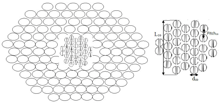
Figure 1. Proposed PCF and its core region.
Consider Wco refers to the distance between two adjacent D shaped air hole. But when two D shaped air hole cemented together seems to be circle with diameter Dco, however Wco evaluate the porosity of each circle. The mathematical expression for porosity as follows:

As Aco is the distance between two centre of adjacent circle and chosen to be Aco=Lco/3.1. In core region, all the circle is array in a triangular lattice. We choose dco/Aco=0.9 as constant value for all simulation. Similarly, in a cladding region all the elliptical air hole is array in triangular lattice also where we choose pitch Acl=Lco/1.43 which represents the midpoint between two elliptical air hole. If dcl is the diameter of cladding air holes and size of air hole in cladding region are same. The air filling ratio of cladding is assumed to be dcl/ Acl=0.95 i.e., more convient for simulation and it may change during simulation process. We choose a suitable background material of proposed PCF as TOPAS (a precious stone). As per experiment data the refractive index and the absorption coefficient of TOPAS are 1.531 and 0.2 cm-2 at the range of 0.5-5 THz.
We have investigated a novel PCF structure in which d shaped air hole in core region and elliptical air hole in cladding region for terahertz criterion. In addition, we adopted PML boundary condition around the cladding region and whose thickness is 10% of the whole PCF radius such that it is not hamper the effective calculation. The electric mode field distribution of PCF design is shown in Figure 2 having porosity is 87%, 75%, 62%, 49%, 43% at 1 THz and it is observed that electromagnetic field is more restricted to the PCF core and very crucial for effective transmission of THz.
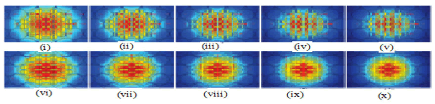
Figure 2. Electric field distribution of proposed PCF of x polarization (i to v) and y polarization (vi to x).
Birefringence is one of the important properties of any PCF. It is highly influential for polarization maintaining fiber. This type of property of PCF comes from source of geometry of asymmetry based on air holes’ position. It is observed that highly structural asymmetry of PCF produces higher order birefringence and structural symmetry of PCF has no influence to produce birefringence. The mathematical formulation of it can be expressed as follows:

it is also expressed as

Where Re(nxeff) and Re(nyeff) are the real parts of the effective refractive index of the fundamental mode of x and y polarization respectively. We have made a novel PCF design for variation of birefringence involving cladding air filling ratio with frequency shown in Figure 3.
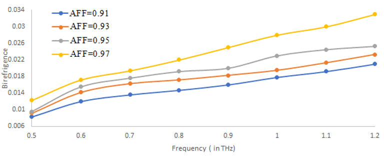
Figure 3. Birefringence versus frequency curve.
The simulation result reveals that the birefringence increases with increasing frequency and air filling ratio. As AFF increases, the light contraction at the core region will increase. Thus, birefringence increase. It is also seen that if AFF is greater than 0.95. The contribution of cladding to light contraction will decrease, as a result the birefringence rate decrease. Because the excess of AFF on cladding may bring to overlapping of air hole, so we set to 0.95 as maximum. Our proposed elliptical PCF reach better result of birefringence over circular PCF previously reported.
The core length is very crucial property of PCF for birefringence. Figure 4 plots between birefringence versus core length range with different porosity. As core length increases, the background material of PCF core increase which bring the material energy concentrate more on fiber core. As a birefringence gradually increases due to the asymmetry D shaped air hole PCF structure. As core length increase gradually birefringence increases with decrease of porosity. Due to decrease of core porosity, the core asymmetry slowly increases and hence increase in the effective refractive index difference between the polarization modes. It is clear from figure that, our proposed elliptical PCF have good result of birefringence w.r.t core length over previously proposed circular PCF.
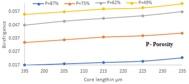
Figure 4. Birefringence versus core length.
We set a core length of 217 μm to evaluate the effective refractive index difference with frequency range for different porosity as shown in Figure 5. The figure plots between the birefringence versus frequency range with different porosity, and the plots offer that birefrigence increases with increasing frequency and reach the value of birefringence 0.0625 at frequency of 1 Hz which is higher value than PCFs reported previously. It is found that, lower porosity (43%) brings the high birefringence effect over higher porosity at 1 THz frequency.

Figure 5. Birefringence versus frequency curve.
This high value of birefringence is most important property of PCF and used for terahertz polarization maintaining and sensing application. Another PCF property is effective material loss play an important role for practical application of THz waveguide and it is due to the dielectric properties of material. To obtain a low loss THz waveguide. EML is expressed as following relation.

Where, αmat be the absorption loss coefficient of bulk material of background material. nmat is the refractive index of material, ε0, μ0 are the electrical permittivity and magnetic permeability at vacuum respectively.
Sz=0.5 × (EXH*) where z is the z component of poynting vector. E and H are the electric and magnetic field.
Figure 6 predicts that, EML versus frequency range with different porosity and it is observed from plot that, EML increase with increasing frequency, however EML decrease with increasing porosity. Due to the increase in porosity the effective material of fiber core decreases, as a result reducing the absorption of background material. Moreover, it reports that the minimum value of x-polarization EML at 0.6 THz is 0.05 cm-1 and the x-polarization EML at 1 THz is 0.061 cm-1. It effectively reduces the absorption loss of material which is less than previous reported PCF such a low EML property of PCF is competently for THz transmission.
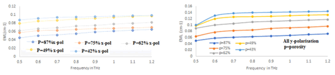
Figure 6. EML versus frequency curve.
Confinement loss is also important property of PCF design, it occurs due to the leaky nature of mode and irregular arrangement of air holes, the air holes are playing the role of dielectric medium. It involves on transmitted wavelength, shape and size, number of air hole rings. Confinement loss can be calculated as the imaginary part of effective refractive index i.e.,

Where Im(neff) is the imaginary part of effective refractive index.
Figure 7 represents the variation of confinement loss versus frequency range with different porosity. It is found that, C.L decrease gradually with increasing frequency range as decrease of porosity. This is due to the reason that core background material increases with decrease of porosity which increase the equivalent refractive index of core, and strictly confine the light to the core, as a result less leakage to the cladding and reduce confinement loss, however is observed that, the low value of C.L indicates higher EML. In fact, the result shows that, this value is lower than that of PCF reported in previously but it is negligible over a EML.
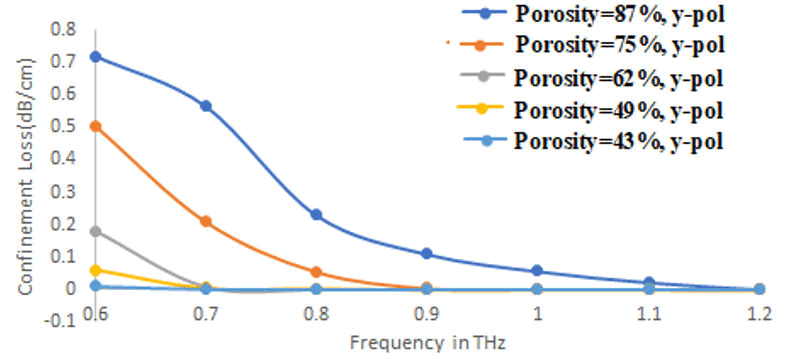
Figure 7. Confinement loss versus frequency.
The property of bending loss is to loss mechanism i.e., coupling to non-propagating modes, it has larger loss for longer wavelength and smaller loss for high NA.
Bending loss is one of the sources of PCF loss. It occurs when the fiber is bent, as a result energy loss of mode take place. Due to this reason that, refractive index inside the PCF is varies by bending and destroy the uniformity of mode field distribution. The refractive index distribution after PCF bending can be expressed as follow:

Where n0(x, y) is the refractive index of cross-section of fiber where there is no bending, R is the bending radius, x is the distance to PCF centre. Figure 8 plots between bend loss versus bending radius with different porosity. It reveals that bend loss gradually decrease with increasing bending radius by reducing porosity.
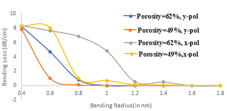
Figure 8. Bending loss versus bending radius.
It is found, that the bending loss of x-polarization is more than that of y-polarization and also shows that smaller bending radius indicates the loss of y-polarization of FM. It is to be noted that when PCF is bent in x direction, so x-polarization mode deviates from the center of fiber core than the y-polarization mode, as a result more is the mode leakage. This flat low bending loss can be used for terahertz transmission and sensing which is lower than PCF reported previously.
The effective mode field area is very important property of PCF which consider as the light carrying region and suggests that lower EMA is preferable for nonlinear application. For fundamental propagating mode, electric field E distribution occur inside the core, as a result EMA of PCF can be estimated by following relation:

Where E (x, y) is the transmission electric field distribution of the fiber section. Figure 9 demonstrate that EMA versus frequency range with x, y polarization of porosity.
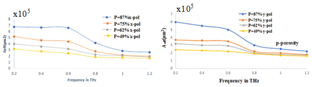
Figure 9. Mode field area versus frequency curve.
It is seen that, EMA decrease with increasing frequency range as porosity decrease. It is very essential to know that with decrease of porosity means equivalent refractive index difference between the design PCF core and cladding will increase, which shows the mode more is limited to the core.
As dispersion being an important parameter of PCF technology that has been studied for a novel proposed PCF, it refers to that the amount of pulse boundary in practical application and is affected by background material and structure of the PCF. As TOPAS being a same refractive index in a frequency range between 0.1-2 THz, so material dispersion is negligible. It is calculated using mathematical formula as follows:

Where ω=2 πf, f is the frequency of light wave, c being the speed of light in vacuum and neff is the effective refractive index of mode.
Figure 10 demonstrates that, the dispersion of proposed PCF versus frequency range for different porosity. It reports a very small value for different porosities and found that between 0.8-1.2 THz. The flat dispersion is 0.9 ± 0.22 ps/THz/cm and very interesting that at operating frequency of 1 THz, the porosity at 62%, The dispersion can be treated as zero, which is better result than the previously reported PCF.
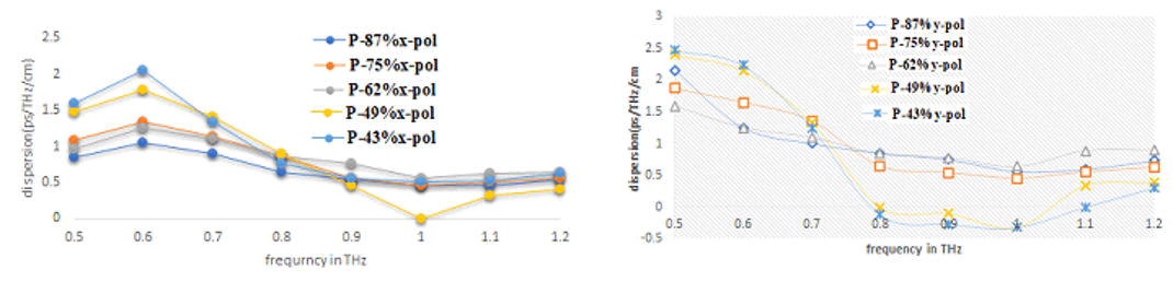
Figure 10. Dispersion versus frequency for different porosity.
Table 1 depicts that the comparison between proposed PCF and the PCF of previous article, it is seen that the proposed PCF has certain merit over previous PCF.
In summary, the motivation of this article is that, our proposed elliptical PCF have reached better result regarding all types of PCF properties such as birefringence, effective material loss, mode field area, bend loss, confinement loss and dispersion over the previously proposed circular PCF. So our proposed elliptical PCF is suitable candidature for full potential in the field of terahertz criterion, maintaining polarization, sensing and applicable for optical communication.
| Reference | Frequency (THz) | Background material | Dispersion (ps/THz/cm) | Birefringence |
| 22 | 1.6 | Topas | 0.47 ± 0.265 | 0.005 |
| 23 | 1 | Topas | 0.9 ± 0.28 | 0.0595 |
| My article | 1 | Topas | 0.9 ± 0.22 | 0.0625 |
Table 1. Comparison between proposed elliptical PCF and previous proposed circular PCFs.
In summary, it reports the performance of a novel proposed PCF for the terahertz region where the guiding properties like high birefringence, low effective material loss, low bend loss, low confinement loss, effective mode field area and dispersion (considered to be zero) are numerically investigated. The proposed PCF offers flat dispersion of 0.9 ± 0.22 ps/THz/cm at 0.8-1.2 THz, a high birefringence of 0.0625, a low effective material loss of 0.061 cm-1 and dispersion can assume to be zero was estimated. In addition, the proposed PCF also shows a very low bending loss of 10-4 dB/cm, an effective mode field area of order of 105 μm2 and a very low confinement loss. The above result shows that the proposed PCF has full potential in the field of terahertz like short distance propagation of terahertz, polarization maintaining fiber, sensing etc.
[Crossref] [Google Scholar] [PubMed]
[Crossref] [Google Scholar] [PubMed]
[Crossref] [Google Scholar] [PubMed]
[Crossref] [Google Scholar] [PubMed]
[Crossref] [Google Scholar] [PubMed]
Journal of Lasers, Optics & Photonics received 279 citations as per Google Scholar report